MainCircuit Wiring
★
★
★
Wiring canonlybedone after themains input is cut off, otherwisetherewill be danger ofelectric
sh o ck!
Onlyqualifi ed and traine d engineer can perform th e wiring, otherwisethere will be danger of
el ectri c sh ock !
Grounding cablemust be grounded, othe rwisethere will be dange rof elec tric shock or fire!
★
★
★
★
Pleaseconfirm thema ins voltage leve l is same with t hat o f thei nverte r,otherwise the inverter
may be dam aged !
Makesure the ratings of the drivenmotor are in compliancewith the inverter, otherwise the
motorma y be da maged or the inv erter maybe in protection st atus!
Do not confuse the i nput terminals with theoutput terminals (U, V, W),ot herwise the re will be
danger of damaging the inverter!
Brake r esistor c an not be c onne cted be tween th e DC bus termin als (+) and (-), o therwis e fi re
mayocc ur!
1
)
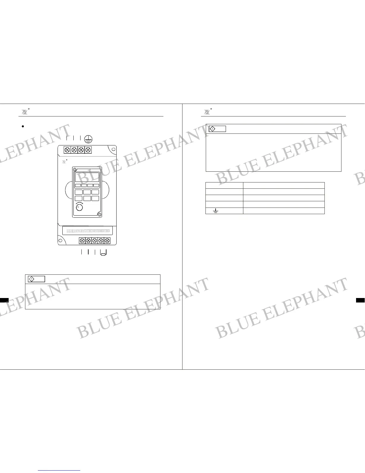
Main Circuit Terminals of Inverter
Terminals
RST(LN)
、、 、
UVW
、、
E
ACinput line terminals
Mo tor connect ion
Ground
Descri ption
BR+ BR-
、
Connectionfor t he braking resistor (option)
2
)
Notes on Wiring
A. Input powe rsupply L and N orR, S a nd T:
There is nophase-ration requirementfor the inputof inverter.
-12-
Danger
Dan ger
C.Brak e re sistor termina ls of BR + BR-
The br a ke resi stor term inal is effec tive only f or th e inverte r of 15 k W or below a nd has a bu ilt-i n bra ke
unit . Select therecommendedresistor with the cable length o flessthan 5m, otherwisethe invertermay
burnor bedamaged.
D. Inve rter output U, V a ndW:
Inverter output terminals cannot connect t o capacit ors or surge snub devices, otherwise the invertermay
be in protecti ve statusor damaged.
If the cables betweenthe motorand t heinverter are too long, electrical resonance may occur due tothe
distr ibut ed capacitance,w hich ma y resultin damaging the mo tori nsulation or big l eaka ge current, so if
the cab le l e ng th is long e r t han 10 0m , AC reactor must b e instal led.
( )、( ):
-11-
INPUT
RT
S
BR+
BR-
R
MOTOR
U
VW
L
()
N
()
Fig.3 -4 Termi nal Diagra m
Cha pt er 3 M e ch anic al and Electri cal Instal lation
DZB Series
Chapter 3 Mechanical and Ele ctrical In stallation
DZB Series
BLUE ELEPHANT
BLUE ELEPHANT
BLUE ELEPHANT
BLUE ELEPHANT
BLUE ELEPHANT
BLUE ELEPHANT
BLUE ELEPHANT
BLUE ELEPHANT
BLUE ELEPHANT
BLUE ELEPHANT
BLUE ELEPHANT
BLUE ELEPHANT
BLUE ELEPHANT
BLUE ELEPHANT
BLUE ELEPHANT
BLUE ELEPHANT
BLUE ELEPHANT
BLUE ELEPHANT
BLUE ELEPHANT
BLUE ELEPHANT
BLUE ELEPHANT
BLUE ELEPHANT
BLUE ELEPHANT
BLUE ELEPHANT