Chap ter 4 Di gital Keyp ad Oper ation
-18-
4.1
Description of the Digital Keypad
●
DigitalKeypadPartsandFunctions
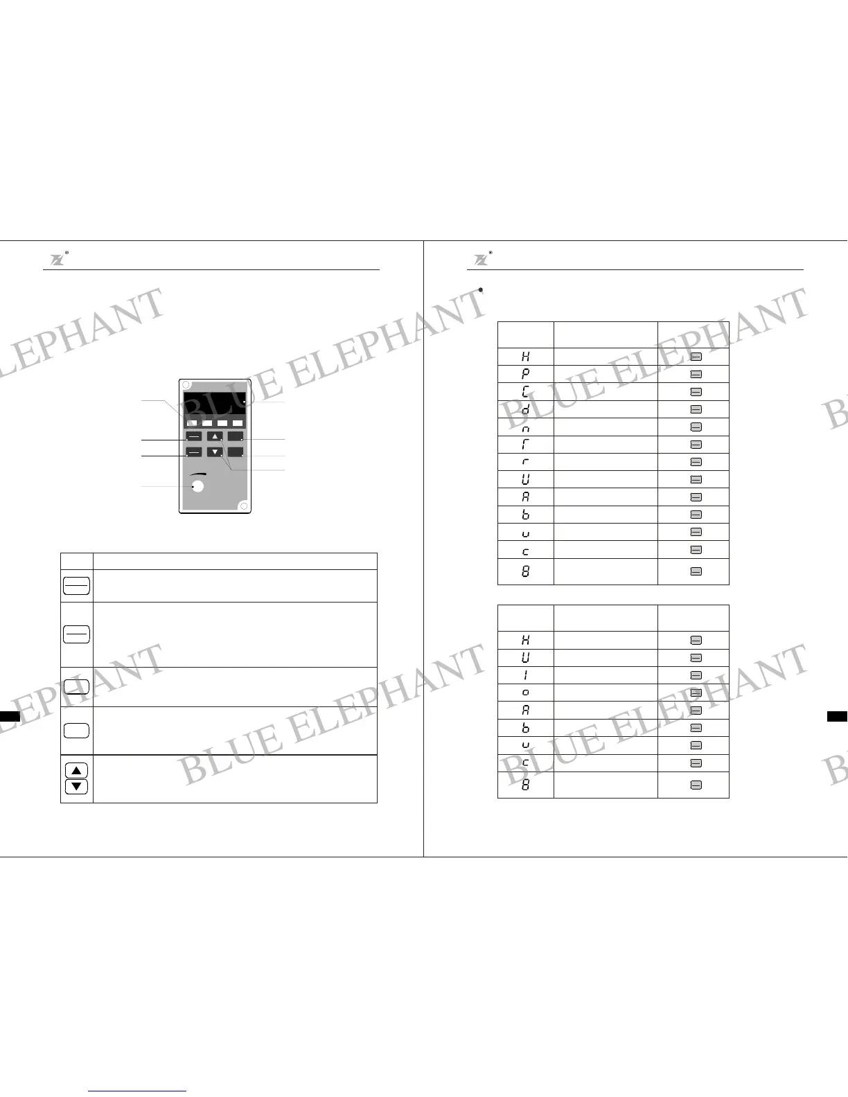
This digital keypad m od ule i nclu de s two parts: di spl a y pa n e l and a keyp a d. Th e displ ay pa ne l
allows th euser toprogram theACdrive, as well as viewthe d ifferent operatingparameters. The
keypad ist he user interface to theAC mo tor drive. Refer to the following f igu refor a description
of the different parts.
Expl anati onof Screen Display
1. ( efer to F 3.05 ):Explanation ofDisplayed Messages o n Runningstatus r
Chap ter 4 Operation and Displa y
DZB Series
Ch a pter 4 Oper a t ion an d Disp la y
DZB S eri es
-17-
FUNC
DATA
Fu nc t ion / Data
Displays information on theA C dri vestatussuch a s the referencefrequency,output
frequency, oroutputcurrentin t he normal mode.While the dri ve is in theProgramMode,
press this key once to disp lay the curr ent parameters.
Af ter c hanging the param e ters , pr e ss thi s k ey again to st or e the new p a rameters .
PRGM
RESET
Program / Reset
First-stagemenuentryor exit.
Key
Description
STO P
Stop
Used t ostop theAC drive operation.
If t heAC drive has stoppeddue to a fa ult,press this button to reset the drive.
Run
Used tostartthe AC driveoperation.
This key has no effect whenthe drive is set to term inal run.
RUN
Up /Do wn
Pressthe "Up" or " Down" but ton to chang e pa ra metersettings.
These keys may also b e us ed to scroll thro ugh differen t operating valu es or paramet ers.
Sett ingfrequency
Running frequency
Outpu t cur rent
Output voltage
Running speed
Actual value of delay time
Setting of delay time
DCbus voltage
PIDse tpoint
PIDfeedback
VI valu e
CI value
Current se gment of
multi-speed contr ol
Ope ration
Displayed
Sym b o l
Displ ayed M essage
QUICK
JOG
FUNC
DATA
Press k e y
“”
QUICK
JOG
FUNC
DATA
Press k e y
“”
QUICK
JOG
FUNC
DATA
Press k e y
“”
QUICK
JOG
FUNC
DATA
Press k e y
“”
QUICK
JOG
FUNC
DATA
Press k e y
“”
QUICK
JOG
FUNC
DATA
Press k e y
“”
QUICK
JOG
FUNC
DATA
Press k e y
“”
QUICK
JOG
FUNC
DATA
Press k e y
“”
QUICK
JOG
FUNC
DATA
Press k e y
“”
QUICK
JOG
FUNC
DATA
Press k e y
“”
QUICK
JOG
FUNC
DATA
Press k e y
“”
QUICK
JOG
FUNC
DATA
Press k e y
“”
QUICK
JOG
FUNC
DATA
Press k e y
“”
2. ( ef e r t o F3.06):Explanation of Displ ayedMessageson Stop status r
CIvalue
VIva lue
Curre nt s egme nt of
mul t i-speed contro l
PID feedbac k
PID s et poin t
Output terminal status
Input terminal s tatus
DCbus v olt age
Setting freq ue nc y
Operat ion
Displayed
Symbol
Displayed Message
QUICK
JOG
FUNC
DATA
Press k e y
“”
QUICK
JOG
FUNC
DATA
Press k e y
“”
QUICK
JOG
FUNC
DATA
Press k e y
“”
QUICK
JOG
FUNC
DATA
Press k e y
“”
QUICK
JOG
FUNC
DATA
Press k e y
“”
QUICK
JOG
FUNC
DATA
Press k e y
“”
QUICK
JOG
FUNC
DATA
Press k e y
“”
QUICK
JOG
FUNC
DATA
Press k e y
“”
QUICK
JOG
FUNC
DATA
Press k e y
“”
F i g.4 -1 Operation P an el Sch ematic Di agr am
Digital display
Display output frequency
current parameter setting
and fault content
、
、
。
Dig ital Ope rator
PRGM
RES ET
FUN C
DAT A
RUN
STOP
STOP
RUN FWD REV
FREQ.SET
8. 8. 8. 8
Funct io n/D ata ke y
Up a nd down keys
Run/move k ey
Stop/ r eset key
Programkey
LED dispaly
Di splay the current running
status of Inverte r:
run stop forward reverse、、 、
Panel poten ti ome ter
BLUE ELEPHANT
BLUE ELEPHANT
BLUE ELEPHANT
BLUE ELEPHANT
BLUE ELEPHANT
BLUE ELEPHANT
BLUE ELEPHANT
BLUE ELEPHANT
BLUE ELEPHANT
BLUE ELEPHANT
BLUE ELEPHANT
BLUE ELEPHANT
BLUE ELEPHANT
BLUE ELEPHANT
BLUE ELEPHANT
BLUE ELEPHANT
BLUE ELEPHANT
BLUE ELEPHANT
BLUE ELEPHANT
BLUE ELEPHANT
BLUE ELEPHANT
BLUE ELEPHANT
BLUE ELEPHANT
BLUE ELEPHANT