Travers e fre quency fun cti o n is su ita bl e to indu strie s suc h as t e x tile, fiber and so on, a nd to ap plica tio n s
whi ch r equire travers ing a ndwindingfunctions.
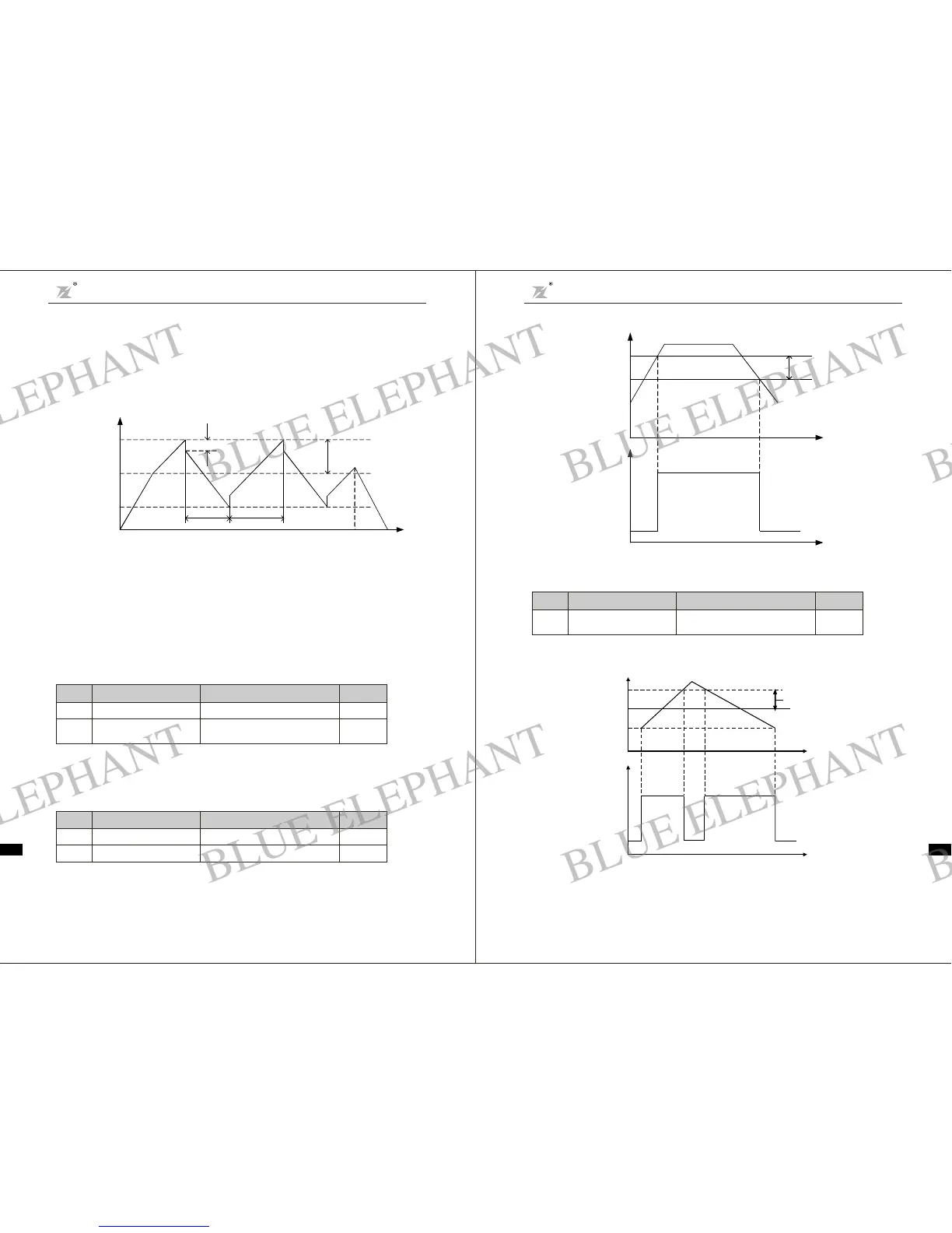
Tra verse frequency functionmeans tha tthe inverter o utput frequency is tr aversi ngup anddown around
the set f requen cy. The oper ating fr equency locus with time axi s i s shown a s fol lowin g di agra m, in whi ch
the amplitude of t raverse is set by F4.07.Whe n F4.07is set to be0, i.e. traverse range i s 0, the traverse
freque ncy functionwill be inactive.
Fig. 6-15Traverse Frequency Ope ration Diagra m
Tra verse frequency range: t rave rseoperat ion frequency limits byupper and lower limit fre quency.
Tra verse range relative to the cent er frequency:amplitude of tra vers e AW = C F AWr ange F4.07
Kic kfrequency = amplit ude of trave rseAW Kick Frequency R ange F4.08. I .e.t he kick frequency is
the value relat ive t o a mpl itu d e of tra ve rs e at traver se- freq uency ope rat ion.
Tra verse frequency r ising time: th e time required to rise from the low est tr averse fr equency to the
highest tra vers e freque ncy.
Tra verse freque ncyfall ti me: the t imere quired t ofa llfrom t he hi ghes ttraversefrequency to the lowest
traversefre quency.
×
×
Fault a uto-reset times:used to set theauto-reset ti mes when inverter chooses fault auto-r es et.If this
val ue is exceeded, inverter will wa itfor t roub le shooting.
Interv al t ime s et ti n g of f a ult auto-r e se t: c ho se th e int e rval time be twe en fault occurring and automa t ic
resett in g a ct u at ed
Set outputfr equency detection value and th e delay value of output ac tiondismissed, as shown by
followingf igure :
When the inverter output frequency reaches th e setfre quency val ue,this function can r eg ulatei ts
detection ra nge value,as shown b yfollowing figure:
Fig.6- 17 Frequency R eac hing Detection RangeDiagram
Fig.6-16 FDT Level Diagram
Operation Frequency
Time t
Deceler ate o n
Deceler ation Time
Traverse Frequency
Fall Time
Tr av erse Frequenc y
Rising T ime
Accelerate on
Acceler a tion Time
Lower Traverse F requency
Center F requency
Upper Traverse F requency
Kick Frequency
FD T delay
Output frequency
Setting fr equency
Fr equency dete ct i on
sign al
Time t
Time t
Detection range(F4.15)
Outputfrequency
Setting frequency
Frequency detection
sign al
Time t
Time t
F4.11
Fault aut o-r eset t imes
03
~
0
F4.12
Interv al t ime setting of
automatic rese tting fa ult
0.1 100 .0 s
~
1.0s
Funct ion
Code
Nam e
SettingRange
Default
Valu e
F4. 1 3
FDT level detectio n va lue
0.00 F 0.04
~
50.00H z
F4.14
FDT delay detection value
0.0 100 .0 % (F D T le v el )
~
5.0%
Funct ion
Code
Nam e
SettingRange
Default
Valu e
F4.15
Freq uenc y rea c hing
detection r ange
0.0 100.0%(maximumfrequency)
~
0.0 %
Fu nction
Code
Name
Setting Rang e
Default
Value
Chapter 6 Parameter D escripti on
DZB Series
Chapter 6 Parameter Descr iption
DZB S eri es
-57- -58-
BLUE ELEPHANT
BLUE ELEPHANT
BLUE ELEPHANT
BLUE ELEPHANT
BLUE ELEPHANT
BLUE ELEPHANT
BLUE ELEPHANT
BLUE ELEPHANT
BLUE ELEPHANT
BLUE ELEPHANT
BLUE ELEPHANT
BLUE ELEPHANT
BLUE ELEPHANT
BLUE ELEPHANT
BLUE ELEPHANT
BLUE ELEPHANT
BLUE ELEPHANT
BLUE ELEPHANT
BLUE ELEPHANT
BLUE ELEPHANT
BLUE ELEPHANT
BLUE ELEPHANT
BLUE ELEPHANT
BLUE ELEPHANT