Electric IOM
14
Electrical Requirements
1. Connect wiring as shown in the specific
wiring diagram which is furnished inside
the cover of the electrical control box. Be
sure to install a separate fused
disconnect for the boiler. All wiring must
conform to NEC Code.
WARNING
Prior to powering up the boiler, all electrical
contacts require re-torquing to the
individual compenents manufacturers
recommendations.
2. A correctly sized fused disconnect switch
should be fitted as close to the boiler as
possible and connections made to the
boiler control panel in compliance with
NFPA (National Fire Protection
Association), NEC Code, and local
codes. The appropriate number of
terminals are provided inside the control
panel box to take these connections, but
the panel box must be drilled to accept
the type of conduit used.
Boiler Controls
Fulton packaged electric steam boilers are
equipped with both a steam pressure
control and a high limit pressure control
mounted on the outside or inside of the
electrical panel box.
1. The steam pressure control should be
adjusted to suit the boiler application.
The control has two scales (main and
differential) which can be adjusted by
means of screws on top of the control.
The main scale setting should be
adjusted to the desired operating steam
pressure.
CAUTION
Do not adjust to exceed the pressure
rating on the boiler.
2. A high limit pressure control is located
next to the operating steam pressure
control and should be set 5 to 10 pounds
higher than the operating steam
pressure control. This control serves as
a secondary high pressure cut-off if for
some reason the main operating steam
pressure control should become
inoperative.
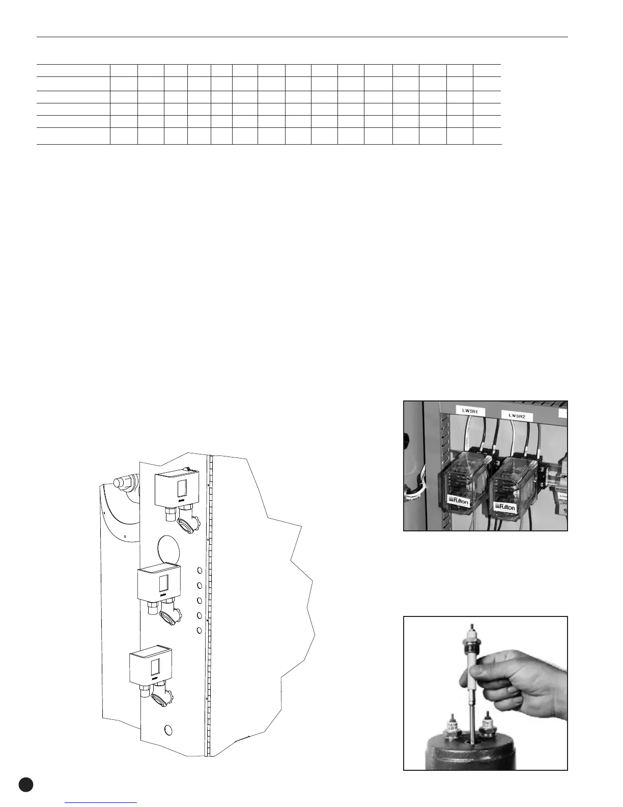
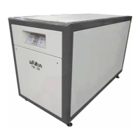
Low Water Control
Relays
1. Boilers from 1.2 to 3.6 HP are e quipped
with one low water cut off relay in the
panel box connected to two
independent probes in the top of the
boiler and one water level control relay
in the panel box operating two probes in
the top of the boiler.
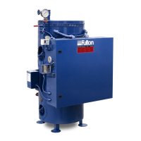
2. Boilers from 5 - 20 HP contain two low
water cut off relays in the panel box
connected to two independent probes in
the top of the boiler.
3. Boilers from 30 - 100 HP have an
external water column on the right hand
side of the boiler. There are two low
water cut off control relays in the panel
box. One connects to a probe in the top
of the boiler and the other connects to a
probe in the top of the water bottle.
Installation
Electrical Power Requirements (In Amps)
Model FB-L 012 015 018 024 030 036 050 075 100 150 200 300 500 750 1000
208V 3 Phase 34 42 50 67 84 100 139 208 278 416 556 832 -- -- --
230V 1 Phase 52 65 78 -- -- -- -- -- -- -- -- -- -- -- --
230V 3 Phase 29 36 43 58 73 87 120 180 241 361 482 724 -- -- --
460V 3Phase 15 18 21 29 36 44 60 90 120 180 241 363 607 906 1204
575V 3 Phase 13 16 18 24 30 36 50 76 101 150 201 301 502 756 1004