Do you have a question about the FUNAI DPVR-2605 and is the answer not in the manual?
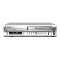
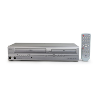
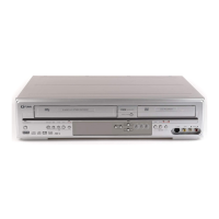
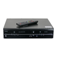
| Type | DVD VCR Combo |
|---|---|
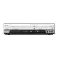
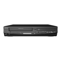
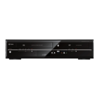
| Brand | FUNAI |
| Model | DPVR-2605 |
| Video Format | NTSC |
| Recording Formats | VHS |
| Number of VCR Heads | 4 |
| VHS Formats | VHS, S-VHS |
| Output Resolution | 480p |
| Audio Output | Stereo |
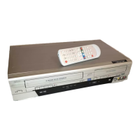
| Remote Control | Yes |
| DVD Player | Yes |
| VCR Player | Yes |
| Playback Formats | DVD Video, CD Audio, Video CD |
| Playable Disk Types | DVD, CD |
| Playable File Formats | JPEG, MP3 |
| DVD Formats | DVD-Video |
| Connections | Composite Video Output |
Technical specifications for VCR and DVD sections, including video, audio, and tuner parameters.
Warnings and procedures for safe handling of laser beams emitted by the DVD pickup.
General safety guidelines for servicing electrical and mechanical parts to prevent hazards.
General guidelines, symbols used in schematics, and handling of ICs and connectors.
Steps to enter service mode and handle optical sensors and REC-Safety switch.
Flowchart and method for dismantling the unit's cabinet and components for servicing.
Procedures for performing head switching position adjustment using test equipment.
Instructions for updating the device's firmware using a disc and remote control.
Schematic representation of the VCR system control blocks and associated components.
Oscilloscope waveforms for key test points, illustrating signal characteristics.
Diagrams illustrating the electrical connections between unit sections and assemblies.
Detailed pinouts and functions for key integrated circuits used in the VCR section.
Visual identification of common semiconductor lead configurations and their functions.
Service schedule for deck components, indicating periodic checks and changes.
List and images of specialized tools required for mechanical alignment procedures.
Step-by-step guide for manual tape loading, unloading, and cassette holder positioning.
Procedures for aligning gears and levers in the tape loading/unloading mechanism.
Visual breakdown of the unit's cabinet and major assemblies with reference numbers.
List of all mechanical components with their reference numbers, descriptions, and part numbers.
List of electrical components, particularly capacitors and diodes, with part numbers.
List of mechanical parts specific to the deck mechanism, including combinations.