Do you have a question about the FUNAI HDR-A2835D and is the answer not in the manual?
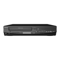
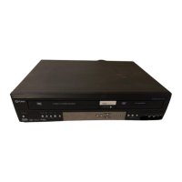
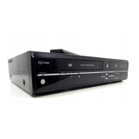
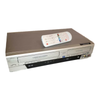
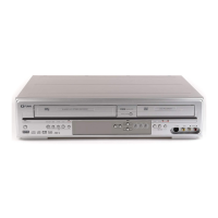
Detailed technical specifications for the DVD/Video Cassette Recorder with HDD.
Warnings and procedures related to the laser pickup's safety.
General safety guidelines for servicing and product handling.
General instructions for circuit board indications, soldering, and connectors.
Specific guidelines for safely handling and maintaining the Hard Disk Drive.
Steps required to prepare the unit for servicing operations.
Step-by-step instructions for safely disassembling the unit's cabinet.
Procedures for performing electrical adjustments and alignment.
Guide to performing self-checks and initializing the device's HDD.
Instructions for updating the device's firmware.
Explanation of symbols displayed on the unit to indicate status.
Visual representation of the servo/system control and sub-system architecture.
Detailed circuit diagrams, component layouts, and test point locations.
Examples of signal waveforms for testing and analysis.
Diagrams illustrating the interconnection of components and units.
Detailed pinouts and functions for key integrated circuits.
Visual guides for identifying semiconductor leads and pin configurations.
Visual breakdown of the unit's components for assembly and disassembly reference.
List of all mechanical parts with their respective reference numbers and part codes.
List of all electrical components including capacitors, resistors, diodes, etc.
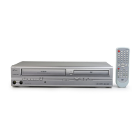
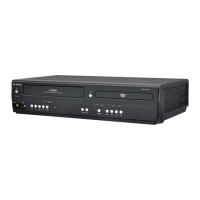
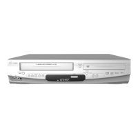
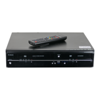
| Type | DVD VCR Combo |
|---|---|
| Video Format | NTSC |
| Recording Formats | VHS |
| DVD Formats | DVD-Video, DVD-R, DVD-RW, DVD+R, DVD+RW |
| Output Resolution | 480i, 480p |
| HDMI Output | Yes |
| Composite Video Output | Yes |
| S-Video Output | Yes |
| Component Video Output | Yes |
| Digital Audio Output | Coaxial |
| Analog Audio Output | Stereo RCA |
| USB Port | No |
| Remote Control | Yes |
| Playback Formats | DVD, VHS |
| Playable Media Format | DVD+R, DVD+RW, DVD-R, DVD-RW, CD-R, CD-RW |
| VHS Formats | VHS |