Do you have a question about the FUNAI DRV-A3635 and is the answer not in the manual?
Detailed specifications for the VCR section, including video, servo, audio, and tuner parameters.
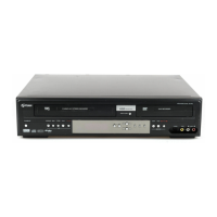
Detailed specifications for the DVD section, including video, audio, and tuner parameters.
Safety measures for servicing, including part replacement, wiring, and general handling.
Procedures for verifying clearance distance and leakage current after repair.
Procedure to enter the service mode for the unit, involving tape and connector manipulation.
Flowchart detailing the steps for disassembling the unit's cabinet to access internal parts.
Detailed method for disassembling specific parts, referencing figures and part locations.
List of required test equipment, including oscilloscope and alignment tape.
Procedure to adjust head switching position during playback to prevent noise or jitter.
Diagram showing the interconnections between the servo, system control, and various assemblies.
Description of pin functions for the IC501 servo and system control IC.
| Remote Control | Yes |
|---|---|
| Number of heads | 4 |
| Recording Formats | VHS |
| Tuner | Yes |
| Power Consumption | 15W |
| Recording Speed | SP, LP |
| Connections | Composite Video |
| Playback Formats | VHS |
| Inputs | Composite Video |
| Outputs | Composite Video |
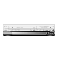
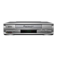
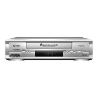
| Type | VHS VCR |