EasyManua.ls Logo

FUNAI DRV-C3835 User Manual

FUNAI DRV-C3835
85 pages
To Next Page IconTo Next Page
Page #1 background imageLoading...
Page #1 background image
SERVICE MANUAL
DVD RECORDER &
VIDEO CASSETTE RECORDER
DRV-A3635
Main Section
I Specifications
I Preparation for Servicing
I Adjustment Procedures
I Schematic Diagrams
I CBA’s
I Exploded views
I Parts List
When servicing the deck
mechanism, refer to MK14 Deck
Mechanism Section.
Deck Mechanism Part No.:
N25E0FL
PAL
SECAMPAL
DRV-C3835
www.freeservicemanuals.info
3/21/2018
Digitized in Heiloo Netherlands
Question and Answer IconNeed help?

Do you have a question about the FUNAI DRV-C3835 and is the answer not in the manual?

FUNAI DRV-C3835 Specifications

General IconGeneral
Video FormatNTSC
DVD PlayerYes
VCRYes
Number of Discs1
Remote ControlYes
Playback FormatsDVD-R, DVD-RW, CD-R, CD-RW
Recording FormatsDVD-R, DVD-RW
Recording SpeedSP, LP, EP
Playback FeaturesRepeat
InputsComposite Video, S-Video, Audio (RCA)
OutputsComposite Video, S-Video, Component Video, Audio (RCA)
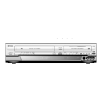
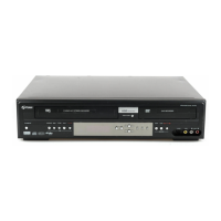
TypeDVD Recorder/VCR Combo

Summary

FUNAI DVD RECORDER & VIDEO CASSETTE RECORDER DRV-A3635/DRV-C3835

MAIN SECTION

Specifications (VCR Section)

Detailed technical specifications for the VCR component of the device.

Specifications (DVD Section)

Detailed technical specifications for the DVD component of the device.

LASER BEAM SAFETY PRECAUTIONS

IMPORTANT SAFETY PRECAUTIONS

Product Safety Notice

Notice regarding special safety characteristics of electrical and mechanical parts.

Precautions during Servicing

Guidelines for safe servicing procedures, emphasizing critical parts and wiring.

Safety Check after Servicing

STANDARD NOTES FOR SERVICING

How to Remove / Install Flat Pack-IC

Step-by-step instructions for handling surface-mount integrated circuits.

Instructions for Connectors

Precautions when connecting and disconnecting flexible flat cables.

Instructions for Handling Semi-conductors

PREPARATION FOR SERVICING

How to Enter the Service Mode

Procedure to access the device's service mode for adjustments.

CABINET DISASSEMBLY INSTRUCTIONS

Disassembly Method

Detailed table listing parts and their removal steps with figure references.

ELECTRICAL ADJUSTMENT INSTRUCTIONS

Head Switching Position Adjustment

Procedure for adjusting head switching for optimal playback quality.

HOW TO INITIALIZE THE DVD RECORDER & VCR

FIRMWARE RENEWAL MODE

BLOCK DIAGRAMS

Servo/System Control Block Diagram

Shows the interconnected components of the servo and system control circuitry.

Digital Signal Process Block Diagram

Video Block Diagram

Video Input Select Block Diagram

Video Output Select Block Diagram

Audio Block Diagram

Audio Input/Output Select Block Diagram

Hi-Fi Audio Block Diagram

Power Supply Block Diagram

SCHEMATIC DIAGRAMS / CBA's and TEST POINTS

WAVEFORMS

WIRING DIAGRAM < VCR SECTION >

WIRING DIAGRAM < DVD SECTION >

IC PIN FUNCTION DESCRIPTIONS

EXPLODED VIEWS

MECHANICAL PARTS LIST

ELECTRICAL PARTS LIST

Related product manuals