Do you have a question about the FUNAI 31A-664 and is the answer not in the manual?
General safety information regarding electrical and mechanical parts.
Specific safety steps and considerations for handling components during repair.
How to identify pins and connectors on circuit boards.
Instructions for using lead-free solder during servicing.
Step-by-step guide for safely removing and installing flat pack ICs.
Detailed technical parameters for video, servo, audio, and tuner sections.
Instructions on how to enter the VCR service mode using optical sensors.
Flowchart and method for disassembling the VCR cabinet and chassis.
Procedure for Head Switching Position Adjustment during playback.
Procedure to restore the VCR to its factory default settings.
Explanation of symbols displayed on the VCR indicator panel.
Servo/System Control, Video, Audio, Hi-Fi Audio, and Power Supply block diagrams.
Notes and warnings for interpreting schematic diagrams and component identification.
Visual representations of key VCR signals for troubleshooting.
Overall connectivity diagram showing major assemblies and connectors.
Detailed pinout and function for the Servo/System Control IC (IC501).
Diagrams showing pin configurations for common semiconductors.
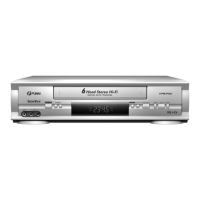
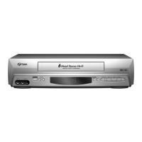
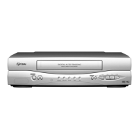
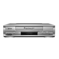
Visual breakdown of the VCR's front panel and cabinet components.
List of mechanical components with part numbers and descriptions.
List of electrical components (capacitors, resistors, diodes, etc.) with part numbers.
| Model | 31A-664 |
|---|---|
| Category | VCR |
| Tape Format | VHS |
| Tuner | Yes |
| Remote Control | Yes |
| Playback Speed | SP, LP, EP |