7-5
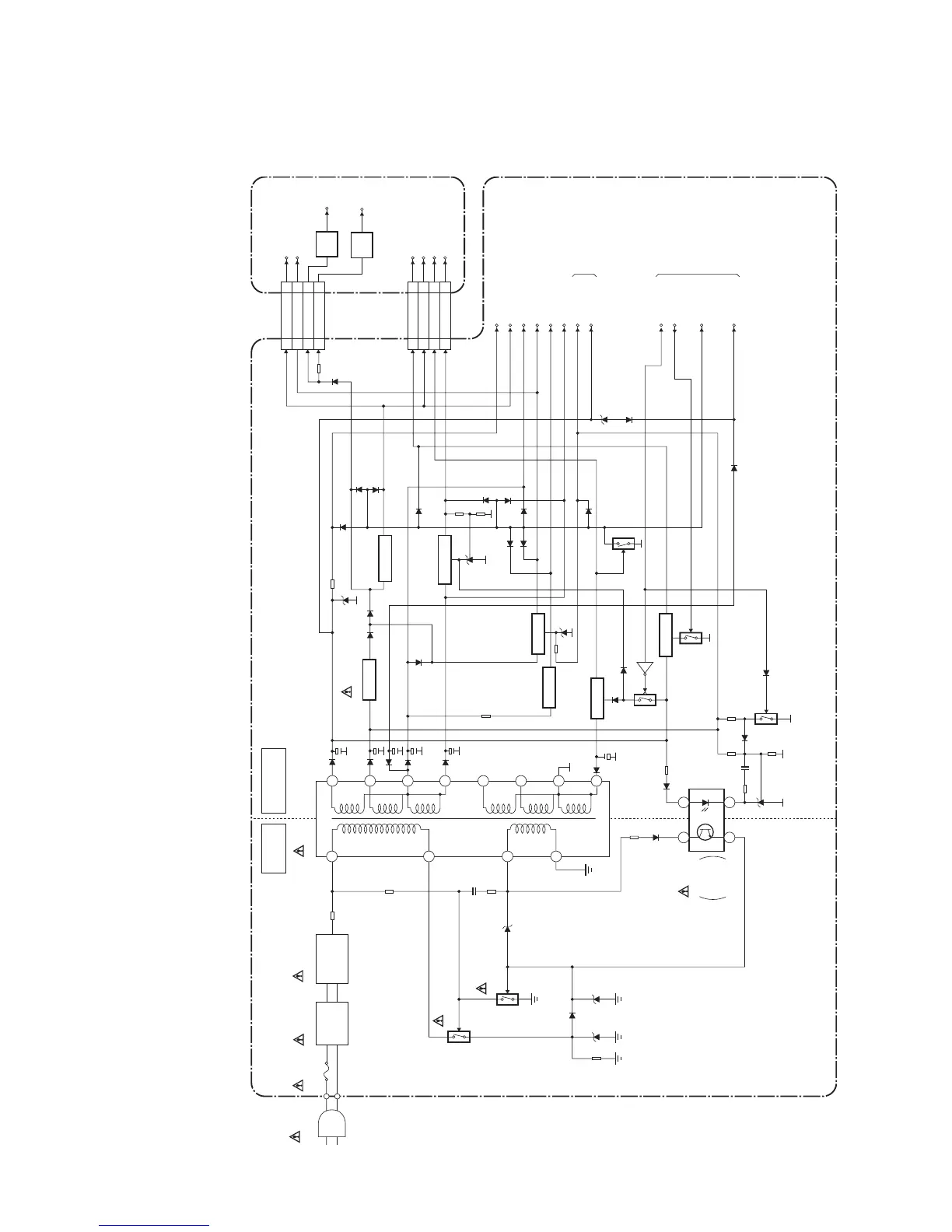
L4620BLP
Power Supply Block Diagram
LINE
FILTER
L601
AC601
AC CORD
BRIDGE
RECTIFIER
D605-D608
HOT COLD
T601
9
11
12
13
10
16
4
4
3
1
2
MAIN CBA
CN101A
HOT CIRCUIT. BE CAREFUL.
2
6
7
AL+33V
AL+3.3V
AL+7.5V
INV+22V
P-ON-H
P-25V-ON
AL+5V
15
14
IC601
IC606
ERROR
VOLTAGE
DET
T-ON+5V
CN103A
AL+12V
PROTECT-1
CN101B
PANEL+25V
66
PANEL+3.3V
33
PANEL+10.8V
11
PANEL+25V
PANEL+3.3V
LCD MAIN CBA UNIT
PANEL-6V
99PANEL-6V
PANEL+10.8V
CN103B
AL+4V(D)13 13
AL+5V(D)12 12
AL+3.3V10 10
REG+3.3V
REG+1.8V
AL+3.3V
IC101
+3.3V
REG
IC102
+1.8V
REG
AL+40V
TO SYSTEM CONTROL
BLOCK DIAGRAM
TO INVERTER
BLOCK DIAGRAM
F601
T4A L 250V
Q608
Q603
Q504
Q633
Q502
Q632
Q507
Q506
-6V REG.
+5V REG.
IC602
+3.3V REG.
IC605
+5V REG.
+5V REG.
Q501
+25V REG.
Q503
+10.8V REG.
Q505
PROTECT-2
AL+5V11 11 AL+5V
CAUTION !
Fixed voltage (or Auto voltage selectable) power supply circuit is used in this unit.
If Main Fuse (F601) is blown , check to see that all components in the power supply
circuit are not defective before you connect the AC plug to the AC power supply.
Otherwise it may cause some components in the power supply circuit to fail.
CAUTION !
For continued protection against fire hazard,
replace only with the same type fuse.