Do you have a question about the Furuno 1722 and is the answer not in the manual?
This document provides comprehensive setup and configuration instructions for the Furuno NavNet series, encompassing 7-inch and 10.4-inch displays, and various peripheral devices such as GPS antennas, radar systems, network sounders, and weatherfax units. It details the steps required for initial installation, network integration, and fine-tuning of each component to ensure optimal performance and functionality.
The guide begins with connecting the GPS position source, which can be a Furuno BBWGPS antenna, a Furuno GP32, or any compatible external device that outputs NMEA sentences GGA, VTG, and ZDA. For the BBWGPS antenna, specific menu navigation steps are provided: accessing "SYSTEM CONFIGURATION," then "NAV OPTION," "NAV SOURCE SETTINGS" to set "POSITION SOURCE" to "FURUNO BB GPS." Further configuration involves "GPS SENSOR SETTINGS," "WAAS SETUP" to enable "WAAS MODE," and "PORT SETUP" to set "FURUNO GPS SENSOR" to "YES." If an external GPS device like the Furuno GP32 is used, the NavNet display's default menu settings are typically sufficient. The BBWGPS antenna connects directly to DATA1 of the display, while the GP32 uses a supplied cable (I/O) and an additional cable (part # 000-144-418) for connection.
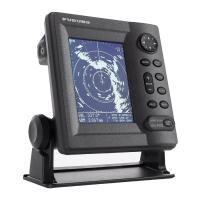
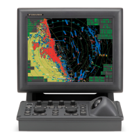
For radar systems, the guide outlines the connection of the radar antenna to DJ1 of the radar display (e.g., 1833C, 1933C, 1943C, 1953C for 10.4-inch displays, or 1722/C, 1732/C, 1742/C, 1762/C for 7-inch displays). Accessing the "Installation Menu" is crucial, which is done by pressing and holding [MENU] while powering on the display. Within "SYSTEM CONFIGURATION" and "INSTALLATION SETUP," the "RADAR SETUP" section requires specific adjustments. "ANTENNA TYPE" must be selected based on the radar model (e.g., A for 1823C, B for 1833/1833C). "ANTENNA ROTATION" should remain at [ROTATE].
After initial setup, the radar must transmit for 5 minutes on the shortest range with proper gain and sea control before proceeding with further adjustments. These include "TUNING" (setting to [ON]), "VIDEO ADJUST" (setting to [ON]), and "TIMING ADJUST" (setting to [ON] and rotating the knob to straighten a long straight target). "HEADING ADJUST" is also detailed, noting a factory setting of 180° out for 24" dome antennas, requiring adjustment to bisect a radar target within a 0.125-.25nm range. The guide also mentions that maximum radar ranges may need to be turned on via [MENU] and [RADAR RANGE SETUP] after changing the antenna type.
The document covers the setup for Furuno BBFF1 and BBFF3 network sounders. The BBFF1 is described as "Plug and Play," connecting to the display's "network port" using a blue 000-144-422, 5m network cable. For displaying digital temperature and depth from the BBFF1, users need to access [MENU], [SYSTEM CONFIGURATION], [GENERAL SETUP], and set "TEMPERATURE SOURCE" and "DEPTH SOURCE" to [ETR] (for transducers with temperature sensors).
The BBFF3 sounder configuration is more detailed, especially for multiple installations. For a single BBFF3, users must connect it with power OFF, remove the cover, and set "TAP H" (High) and "TAP L" (Low) according to the chart inside the cover, confirming these settings in the NavNet display menu. The "HOST NAME" switch on the front panel should be set to "0," and then power is turned ON. NavNet display configuration involves accessing [MENU], [SYSTEM CONFIGURATION], [INSTALLATION SETUP], [NETWORK SETUP], and confirming "SOUNDER SOURCE" is "SOUNDER." For preprogrammed transducers, "TRANSDUCER SETUP" allows selection of "MODEL NUMBER" and "HIGH/LOW FREQUENCY" with appropriate transducer and tap settings. For other transducers, "MANUAL" selection allows setting specific frequencies (25-220).
For multiple BBFF3 installations (up to two network sounders), the master BBFF3 (with highest power and lowest frequency) is set up first, then powered OFF. The second BBFF3's "HOST NAME" switch is set to "0," configured, then powered OFF. Finally, the second BBFF3's "HOST NAME" switch is set to "1," and both units are powered ON. The display's "soft keys" are used to select between "SOUNDER SOURCE," with the master being "SOUNDER" and the second "SOUNDER1." If a BBFF1 is installed with a BBFF3 master, the BBFF3's "HOST NAME" switch is set to "1" to retain settings, and the BBFF1 becomes "SOUNDER" while the BBFF3 becomes "SOUNDER1."
Maintenance features for BBFF3 include erasing transducer settings (by pressing and holding S1 (TDCLR) on the CPU board until the TX/STBY LED flashes) and a master reset (by locating and jumpering J9 pins 5&6 while reapplying power).
For multiple component configurations with 10.4-inch and 7-inch displays, the guide emphasizes connecting and configuring a single display and network sounder first. It reiterates confirming no simulation modes are selected. Up to four 7-inch and/or 10.4-inch displays can be used in the network, along with other network devices like BBFF1, BBFF3, or FAX30. A standard Ethernet hub is required for three or more network devices, ensuring a stable 12VDC supply to the hub.
Crucially, all displays must have a different "HOST NAME" and "IP ADDRESS." While a two-display system usually corrects automatically, three or more displays require manual configuration via [MENU], [SYSTEM CONFIGURATION], [INSTALLATION SETUP], and "NETWORK SETUP." Users are advised not to rename the "RADAR" display. All displays must input their [HOST NAME] on the network, omitting their own.
For plotter displays, if a BBFF1 is installed, users are directed to the "single display setup page" for temperature and depth display. General function and display parameters are set using the "NavNet General Information" page and operator's manual. "CHART SOURCE" requires adding RADAR under the NETWORK SETUP menu.
The FAX30 Weatherfax Quick Reference details its setup and features. It can be connected via an external GPS or a 6-meter whip/wire antenna, or a 2.6-meter whip antenna with an optional FAX5. The FAX30 is accessible 15 seconds after power-on and viewable on a NavNet 10.4-inch color display and/or PC. For PC viewing, users open a web browser and enter the IP address 172.31.8.1, with an important note to "Log off" when done viewing. The FAX30 stores a maximum of 12 images and receives one fax image or Navtex message at a time. It supports three modes: FAX, Navtex only, or FAX (timer) & Navtex. It lacks an internal clock, receiving time from NavNet "ZDA" sentences or a PC. Auto Navtex mode requires navigation data.
For FAX5 antenna coupler with an 8' whip antenna, jumper J23 on the RCV board must be set to "ACTIVE." Long wire antennas do not require internal jumper changes. Antennas should be located away from TX antennas, noise-generating equipment, rigging, and masts.
Maintenance for FAX30 includes a master reset procedure: unplugging, removing cover, setting S1 #1 "on," connecting power, confirming LED flashing, then turning off, disconnecting power, setting S1 #1 "off," and reassembling.
Navtex notes include storing 130 messages, beginning with ZCZC (ID) and ending with NNNN. Message categories are selectable, with recommended minimums being Coastal navigational warning (A), Meteorological warning (B), Search and Rescue Alert (D), and Navarea warnings (L).
The "NAVNET GENERAL INFORMATION" section provides radar setup for manual tuning to achieve maximum detection. This involves adjusting SEA and RAIN controls to off or minimum, setting A/C AT [OFF], and then adjusting GAIN to maximum, slowly reducing it until only small amounts of noise appear. This procedure establishes a reference for comparing with automatic gain, sea, and rain functions.
Heading input can be connected to the NavNet RADAR DISPLAY only, automatically shared on the network. AD10 (Furuno 4-wire) connects to the heading port, while NMEA (2-wire) connects to the heading input or any NMEA port. If using NMEA heading, the radar display's [OUTPUT THROUGH NETWORK] port must have HDG "ON" for network sharing. Heading is required for radar chart overlay, waypoint mark, echo stretch, radar north-up, course-up, true motion, and the optional ARP11 (automatic radar plotter), which requires FURUNO AD10 heading format.
Time offsets are set in [GPS SENSOR SETTINGS] or [NAV SOURCE SETTINGS]. For BBWGPS, it's set in [LOCAL TIME OFFSET]. For external GPS sources, it's set in [LOCAL TIME OFFSET] for any display with an external GPS source and/or network displays. It's crucial that the time offset is the same for all displays on the network for proper waypoint operations.
Displaying different screen colors is possible, with factory programmed or user selectable "MANUAL" options. Multi-color radar display allows changing "ECHO COLOR" to "MULTI COLOR." Chart color selections depend on the type (C-MAP or Navionics). Pre-programmed or Manual color selections can be enabled by pressing [POWER/BRILL], [HUE] and selecting [DAY], [NIGHT], [TWILIGHT] or [MANUAL].
Multiple display networks allow a maximum of four displays. Chart source allows for three additional HOST NAMES plus the display's own chart source. Other network devices like BBFF1, BBFF3, and FAX30 can be added. "Output Through Network Sentences" must be configured only on the NavNet display with the position source connected, setting GGA, VTG, and ZDA to "ON" for proper position and waypoint operations.
The "NAVNET Wiring Configurations" section provides detailed diagrams for power supply connections (omitted for clarity, referring to installation manuals for details). It illustrates connections for BBWGPS, GP32, VHF Radio, Autopilot, PG1000, and Smart Depth Sensor to various DATA ports on 7-inch and 10.4-inch NavNet displays. It highlights port priorities, with BBWGPS overriding all ports and Network Port having the highest priority for any position data coming into the display.
Throughout the document, a consistent instruction is given: "POWER OFF then ON after any 'MENU CHANGES' to store the new information." This emphasizes the importance of cycling power after making configuration adjustments to ensure settings are saved and applied correctly. The guide also frequently refers to "Wiring configurations" and "General Information" pages or installation/operator manuals for more detailed information, indicating that this document serves as a quick setup guide rather than an exhaustive manual.
| Antenna Rotation Speed | 24 rpm |
|---|---|
| Operating Temperature | -15°C to +55°C |
| Display Size | 7 inch |
| Display Type | LCD |
| Range Scales | 0.125, 0.25, 0.5, 0.75, 1.5, 3, 6, 12 nm |
| Power Supply | 10.8-31.2 V DC |