Do you have a question about the Furuno FAR-1416 and is the answer not in the manual?
Details the functions and layout of the RCU-029 control unit.
Explains the operation of the optional trackball control unit RCU-030.
Describes the functions of the optional remote controller RCU-019.
Instructions for powering the radar system on and off using the control unit.
Explains how to initiate and halt radar transmission using the STBY/TX key.
Covers selecting tuning methods, initialization, and manual tuning procedures.
Guide to choosing between automatic and manual receiver tuning methods.
Procedure to re-initialize automatic tuning if it's not functioning correctly.
Step-by-step instructions for manual receiver tuning using the tuning bar.
Covers adjusting screen brilliance and selecting color tone presets.
Instructions for adjusting screen brilliance using the BRILL knob.
Details adjusting screen brilliance and color tone, listing preset variations.
Explains various radar screen indicators, boxes, and their functions.
Covers cursor information display and selecting cursor functions.
Describes how cursor data (latitude/longitude or X-Y coordinates) is displayed.
Guide to activating cursor-related functions via the [CURSOR] menu.
Covers accessing and operating the main and layered menu systems.
Steps to open and close the main menu on the control unit.
Detailed guide on navigating and operating the layered menu system.
Instructions for text input using the on-screen keyboard and controls.
Explains how to access and operate functions via on-screen box menus.
Instructions for changing the radar's display range scale using keys or box menus.
Guide to changing the radar's pulselength setting via the [PULSE] box.
Guide to changing the radar's pulselength setting via the [PULSE] box.
Covers selecting and describing various radar display modes.
Steps to change the radar display mode (e.g., Head Up, North Up).
Explains various radar presentation modes like Head Up, North Up, etc.
Covers setting operation modes and changing function key assignments.
Instructions for configuring function keys to single or multi-operation modes.
Explains how to use single function keys and lists their preset functions.
Guide to assigning specific functions to the F1-F4 keys.
How to select the source for heading input (gyrocompass, AD-10, serial).
Covers setting own ship's speed automatically or manually.
Steps for automatically setting own ship's speed using log or GPS data.
How to select and display navigational data boxes for own ship information.
Procedure for entering and managing the Man Overboard (MOB) mark.
Covers selecting auto/manual gain and manual adjustment procedures.
Instructions to switch between automatic and manual gain control.
Detailed steps for manually adjusting the receiver gain.
Covers selecting methods and fine-tuning sea clutter reduction.
Guide to selecting manual or automatic methods for sea clutter reduction.
Instructions for fine-tuning sea clutter reduction via control unit or on-screen box.
Detailed steps for manually adjusting the A/C SEA control for clutter reduction.
Covers selecting methods and manually reducing rain clutter.
Guide to selecting manual or automatic methods for rain clutter reduction.
Detailed steps for manually adjusting the A/C RAIN control for clutter reduction.
How to activate and adjust the interference rejector function.
Explanation of the echo stretch feature and how to set its types.
How echo averaging reduces sea clutter and its operational notes.
Covers turning ACE on/off, adjusting gain in ACE mode, and high sensitivity.
Steps to activate or deactivate the Automatic Clutter Elimination (ACE) function.
How to adjust gain when the ACE function is active.
How to select high sensitivity levels when ACE is active.
Procedure to suppress false echoes appearing on the radar display.
How to activate the noise rejector to improve S/N ratio.
Explanation of the wiper feature for reducing weak signals and unwanted echoes.
Covers using zoom functions and selecting expansion.
Guide to enabling, disabling, and using the zoom magnification feature.
How to select the zoom expansion factor (2x or 3x) and display method.
How to move the display center for expanded view without changing range scale.
Explanation of preset radar settings for various navigational situations.
Steps to cycle through and select available customized echo options.
Detailed guide on editing custom echo settings for various parameters.
Procedure to restore previously saved user customized echo settings.
How to restore customized echo options to their factory default settings.
Steps to disable unused picture preset options from being selectable.
How to activate the function to reject false echoes from distant targets.
Explains methods for measuring target range using rings, cursor, or VRM.
Instructions to display or hide the fixed range rings on the radar screen.
Guide to using VRM key or box to measure range to targets.
How to select units (NM, km, SM) for VRM measurements.
How to display Time To Go (TTG) to a selected VRM.
Covers methods for measuring target bearings using EBL.
Explains using the EBL key or EBL box for measuring target bearings.
How to interpret EBL readouts as relative or true bearings.
How to use offset EBL and VRM for assessing collision risk.
Steps to use offset EBL and VRM for assessing collision risk.
How to set the EBL offset origin reference to ground, heading, or north.
Procedure for measuring range and bearing between two targets using EBL/VRM.
Covers displaying target trails, trail time, color, and gradation.
How to set the time interval for plotting target trails on the screen.
How to display target trails in true or relative motion modes.
How to select trail display as single tone or gradual shading.
Instructions for selecting colors for target trails using various methods.
How to select the intensity or afterglow level of target trails.
How to paint target trails with thinner lines for better distinction.
Procedure to temporarily hide trails by setting trail time to OFF.
Instructions for erasing all trails or parts of trails.
How to prevent sea clutter display in true trails.
How to select the duration for which trails are displayed on screen.
Procedure to hide land trails to clear the radar pictures.
How to hold trails at a specified time from TRAIL LENGTH setting.
How to activate trail color shifting to distinguish tracks painted in different colors.
Explanation of the target analyzer function for identifying dangerous targets.
Steps to turn the target analyzer and its hatching feature on or off.
How the target alert function alerts navigators to targets entering specific areas.
Procedure for setting a target alarm zone using points A and B.
How to silence the audio alarm for target alerts.
Procedure to deactivate an active target alert or zone.
How to adjust echo strength, alarm conditions, and audio alarm volume.
Usefulness of PI lines for maintaining constant distance from coastlines or ships.
How to select the maximum number of PI lines to be displayed on screen.
How to adjust PI line bearing and interval on the screen.
How to set PI line bearing reference to relative or true.
How to select PI line orientation as parallel or perpendicular.
How to reset PI lines to default orientation (ship's heading).
Explanation of the net cursor for depicting fishing nets on the radar.
Steps to activate the net cursor for displaying fishing net dimensions.
How to set the dimensions and orientation of the net cursor.
How to use a circle line to measure distance between two points.
Covers heading line, stern mark, north mark, and cursor bearing scale.
How the heading line is displayed and how to erase it temporarily.
How to display or erase the stern mark when it is active.
Where the north mark appears and how it moves with head-up mode.
How to select the display format for the cursor bearing scale.
How to turn on/off and configure the own ship symbol (minimized or scaled).
How to adjust cursor properties like bearing, range, size, and color.
How to set up barge information display with icons.
How to adjust the brilliance of on-screen markers and alphanumeric readouts.
How to change the radar display mode (Standard, Simple, Sea-through).
Covers displaying and setting up navigational data boxes on the screen.
Steps to display and set up navigational data boxes on the screen.
Procedure for setting the radar's local time, adjusting for UTC difference.
Instructions for setting Loran A, Loran C, and Decca chain offsets.
How to customize operational settings like wheel drive direction and key beep volume.
Covers alert descriptions, acknowledgment, and alert list management.
Explanation of different alert levels (alarm, warning, caution) and their meanings.
How to acknowledge alerts and silence the buzzer.
How to display and manage the list of system alerts and their details.
Table explaining the visual and audible meanings of various alert icons.
Covers setting, changing, and disabling the system password.
Procedure for setting or changing the system password for security.
Steps to disable the password protection feature.
Covers basic concepts like minimum/maximum ranges and radar resolution.
Defines minimum and maximum radar detection ranges and factors affecting them.
Explains types of false echoes like multiple echoes, sidelobes, and virtual images.
Explains multiple echoes and how to reduce them.
Explains SART operation, display, and general remarks on receiving SARTs.
Explains how a SART is triggered and appears on the radar display.
How to activate the radar feature to optimally display SART marks.
Covers SART range errors and radar bandwidth considerations.
Explains RACON signals and their appearance on the radar screen.
Explains the function of RTE for improving radar target detection.
Safety warnings and cautions regarding the use of target tracking.
Details TT symbols, their status, and remarks.
Table detailing symbols used for target tracking and their meanings.
Steps to show or hide target tracking symbols on the radar display.
Covers selecting auto/manual trail modes and acquiring targets.
How to choose between manual and automatic target tracking modes.
Step-by-step guide for manually acquiring radar targets for tracking.
How targets are automatically acquired when entering the acquisition zone.
Procedures for cancelling tracking for individual and all targets.
Procedures for cancelling tracking for specific targets using cursor or cancel key.
Steps to cancel target tracking for all acquired targets simultaneously.
How to select mark shape, color, and track color for tracked targets.
How to display and hide detailed data for tracked targets.
Procedure for displaying basic and detailed target information on screen.
How to display and hide the target list showing all tracked TT and AIS targets.
Covers displaying past position points for tracks and changing track color/interval.
Steps to show or hide past position points for tracked targets.
How to select the color and line type for TT tracks.
How to set the time interval for plotting TT tracks.
Explains vector types and how to change vector length/time.
Explains true and relative vectors, and ground/water stabilization.
How to adjust the vector time for target prediction and collision risk evaluation.
How to manually enter set and drift for accurate vector calculations.
Covers lost target alerts and collision alerts (CPA/TCPA).
How to set the lost target alert filter and enable/disable the lost target alert.
How the radar calculates and alerts for potential collisions based on CPA/TCPA.
How the acquisition zone alerts targets and automatically acquires them.
How to simulate target scenarios for collision risk assessment.
Explains AIS symbols used on the radar display.
Steps to display AIS symbols on the radar screen and their meanings.
Covers manually activating targets and automatic activation within range.
Procedure for manually activating sleeping AIS targets.
How to automatically activate AIS targets approaching a specified range.
How to limit AIS auto-activate function based on ship's speed.
How to temporarily hide unnecessary AIS targets from the screen.
Covers setting AIS target color and brilliance.
How to select the color for AIS target marks.
How to adjust the brilliance of AIS target marks.
How to display AIS target data and manage it.
Steps to display AIS target data in the data display area.
How to remove or temporarily hide AIS target data boxes.
How to display detailed information for a selected AIS target.
How to display and hide the AIS target list.
Covers displaying AIS target tracks and setting color/line.
Steps to display the track history for AIS targets.
How to select the color and line type for AIS target tracks.
How to pause or resume the recording of AIS target tracks.
Explanation of vector lines on AIS targets showing speed and course.
Covers AIS target alerts and lost target filters.
How to set proximity alerts for AIS targets within a specified range.
How to filter lost AIS targets based on range, speed, class, or length.
How to set collision alerts based on CPA and TCPA limits for AIS targets.
How to transmit and receive AIS messages and display received messages.
Displays own ship and other ship tracks on the video plotter.
Details symbols for own ship and other ships, including marks and vectors.
How to plot and display the own ship mark and its associated lines/vectors.
How to plot other ship marks and GPS buoy marks on the screen.
Steps to set and display own ship marks and other ship marks.
How to show/hide own ship's tracks and other ships' tracks.
How to hide own ship's track and show/hide it while recording is halted.
How to select track colors by voyage date, water temperature, or depth.
How to select track line type (solid, broken, dashed) for own and other ships.
How to set the recording method and interval for own ship's and other ship's tracks.
Methods to delete own ship's track based on points, range, or all tracks.
How to edit tracks using methods like two points, set range, or within range.
How to display basic and detailed information for other ships.
Methods to delete other ship's tracks by specifying target, color, or line type.
Covers setting marks, entering marks/lines, and editing/deleting them.
Covers setting mark color, shape, line type, size, and fish type.
How to set mark color, shape, line type, and fish type.
How to set the size of marks (Large, Large Dot, Small).
How to assign a fish type to a mark and hide fish marks using the filter.
Three methods for entering marks and lines on the screen.
Methods to delete marks/lines using cursor, set range, within range, or out of range.
Four methods to edit existing marks/lines on the screen.
How to display basic and detailed information for marks on the screen.
How to show/hide marks based on attributes like type, color, shape, or date.
Covers setting origin mark type and stabilization, entering, and deleting marks.
How to select the symbol type for origin marks (Numerical or Symbol).
How to change the stabilization method for origin marks (ground or sea).
How to enter an origin mark using heading and location data.
How to delete an origin mark from the screen or mark box.
Covers entering, editing, deleting, and searching for waypoints.
Seven methods for entering waypoints, including at own ship, cursor, or lat/lon.
How to edit existing waypoints from the waypoints list.
Two methods for deleting waypoints: on the map or from the waypoints list.
How to sort and search waypoints by various criteria.
How to set ship speed for calculating Time To Go (TTG) to a waypoint.
How the waypoint name is indicated on the screen.
How to set the display size for waypoint marks.
How to display waypoints received from external GPS navigators.
Covers creating and editing routes using waypoints.
Three methods for creating routes: with existing waypoints, own ship position, or track.
How to convert a track into a route using start and end waypoints.
How to add new waypoints to an existing registered route.
How to remove a waypoint from a registered route.
How to delete routes from the route list.
How to search routes by sorting or by name.
How to set ship speed for calculating Time To Go (TTG) to a route.
How to display routes received from external GPS navigators.
How to set quick points and registered waypoints/routes as destinations.
How to set quick points as a temporary destination using one or 100 points.
Methods to set a registered waypoint as a destination (on display, list, name, log).
How to set a registered route as a destination, including direction control.
How to temporarily bypass a waypoint in a route and proceed to the next.
How to automatically switch to the next waypoint upon arrival.
How to cancel a set destination waypoint.
Explains waypoint settings like bearing, RNG/BRG mode, arrival time, and overwrite.
Covers setting arrival, anchor watch, route, XTE, border, intrusion, and speed alerts.
How to set arrival and anchor watch alerts based on distance and vessel movement.
How to set route alerts for waypoints within a route.
How to set Cross Track Error (XTE) and border alerts for course deviations.
How to set proximity alerts for approaching waypoints.
How to set alarms for boat speed within or over a specified range.
How to set alerts for traveling a certain distance (trip range).
How to reset the trip range meter to zero.
How to set alerts for water temperature being higher or lower than set range.
How to set tide alerts based on water temperature variation and detection time.
How to set depth alarms when bottom echo is within the alarm range.
Covers displaying, aligning, selecting chart types, and chart settings.
Steps to display or hide the electronic chart on the radar screen.
How to align chart position with radar targets if they are not overlaid correctly.
How to select different chart types (Vector, Fishing, C-MAP, Navionics).
Explanation of various items within the chart settings menu.
How to turn depth contours on/off and select color/line type.
How to display depth lines with a detailed range interval for better visualization.
Explanation of menu items related to chart display and settings.
Overview of saving data to internal memory or USB flash memory.
Covers saving data to internal memory and displaying it.
Steps to save current data to the internal memory.
How to display the data stored in the internal memory.
How to playback data from internal memory, noting it deletes active memory data.
Procedures to delete internal memory data by selecting specific blocks.
Information about using USB flash memory for data backup.
Steps for inserting a USB flash memory into the USB port.
Procedure for safely removing the USB flash memory.
How to save current and internal memory data to USB flash memory.
How to load data from USB flash memory back into internal memory.
Covers automatic and manual data backup methods.
How to set up automatic data backup to USB memory or internal memory.
Steps for enabling periodic automatic data backup.
Steps for enabling periodic automatic data backup to internal memory.
Methods for manually saving data backups to USB memory or internal memory.
How to load backup data from USB flash memory or internal memory.
How to load data from other equipment into internal memory.
How to capture screen data, save it to internal memory, and transfer to USB.
Regular maintenance checks and measures for the radar equipment.
Instructions for replacing the fuse on the display unit's interface board.
Estimated life expectancy for consumable parts like the magnetron and antenna motor.
Procedure for cleaning the trackball if the cursor moves abnormally.
Common problems, causes, and remedies for restoring normal operation.
Covers radar function test and plotter function test.
How to execute a diagnostic test to check major circuit boards.
How to perform a diagnostic test for the plotter functions.
How to check CANbus data and save it to USB flash memory.
How to check the operation and alert log from the log monitor.
Details antenna type, radiator length, beamwidth, and rotation.
Covers frequency, output power, range, and accuracy specifications.
Details screen size, brightness, contrast, view angle, and range scales.
Provides a table of range scales and their corresponding ring intervals.
Lists plotter functions including projection, usable area, memory capacity, and tracking.
Details the number and types of ports on the display unit and data sentences.
Lists available ports like Heading input, Serial I/O, LAN, CANbus, USB, DVI, RGB.
Lists input and output data sentences supported by the system.
Provides specifications for display unit and optional rectifier/power supply units.
Lists operating and storage temperature, humidity, protection degree, and vibration.
Specifies the fixed colors for the antenna unit and display/control unit.
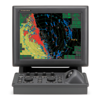
| Display Type | LCD |
|---|---|
| Screen Size | 10.4 inches |
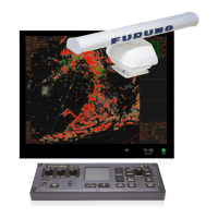
| Antenna Type | Open array |
| Type | X-band |
| Display Size | 10.4 inches |
| Resolution | 800 x 600 pixels |
| Range | 0.125 - 96 NM |
| Antenna Size | 4 feet |
| Antenna Length | 4 feet |
| Frequency | 9410 MHz ±30 MHz |
| Beamwidth | 1.8° |
| Rotation Speed | 24 RPM |