2. WIRING
2-27
2.4 Antenna Unit for S-band, TR-UP Radar
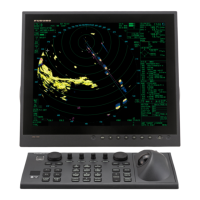
2.4.1 How to fabricate the cables
For how to connect the LAN modular plug, see "LAN cable" on page 2-5. For how to
connect the WAGO connector, see "WAGO connector" on page 2-6.
RW-00135
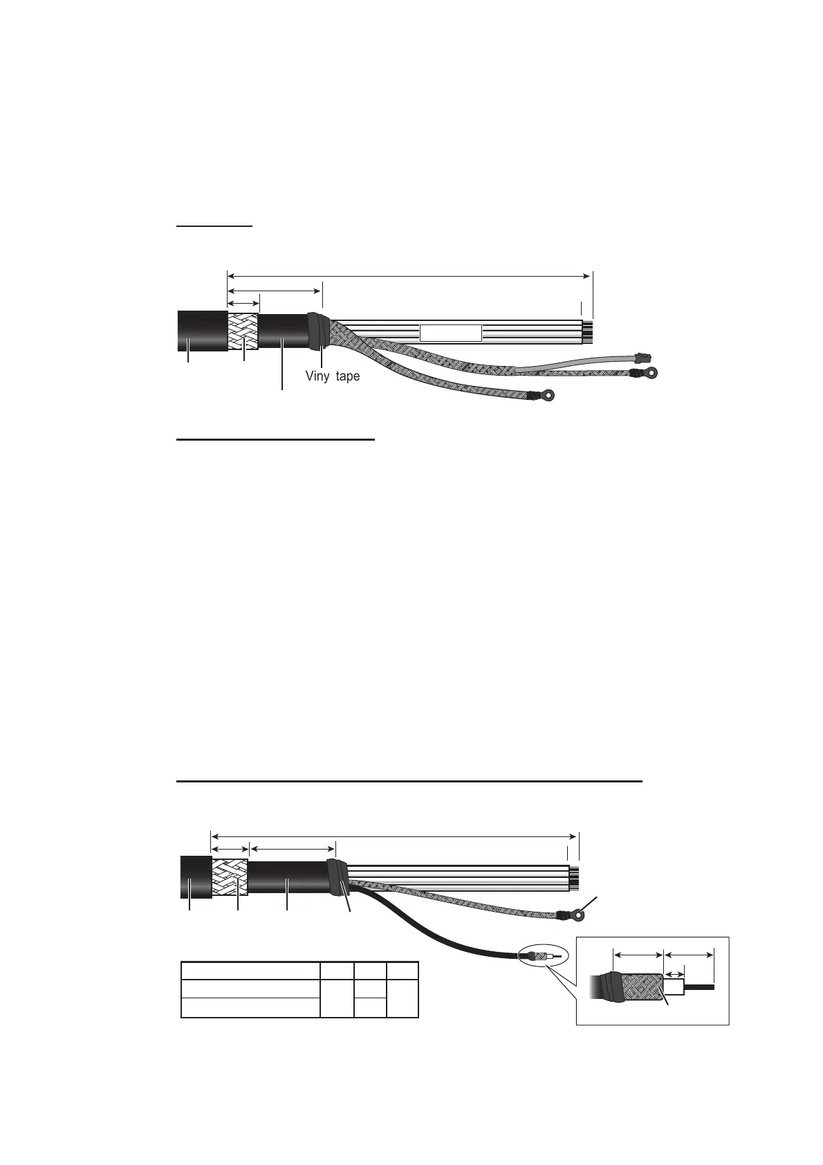
RW-9600/6895 (for retrofit)
To use the existing cable (RW-9600/6895) for the retrofit, two optional kits are re-
quired. For the LAN Coaxial Converter, see section 2.10 "LAN Signal Converter" for
details.
• LAN Signal Converter: Type: OP03-247-2 (for Magnetron radar)
Type: OP03-247-1 (for solid state radar)
• Retrofit Cable Kit: Type: OP03-255-1
Note: The maximum antenna cable length is 100 m for RW-9600, 50 m for RW-6895.
If the existing antenna cable is longer than the above maximum length, replace the
antenna cable with RW-00135.
For cable fabrications and wiring, see the installation manuals in the optional kits.
The unused power lines are tied up and attached to the crimp-on lug FV5.5-S4 (LF),
supplied locally. Connect these unused lines to the ground terminal with the shield
line. See the interconnection diagram at the back of this manual for details.
S03-92-15/30/40/50 (RW-00136 + connector, for a sub monitor)
Note: The maximum cable length is 50 m.
Vinyl tape
Outer
sheath
Armor
Magnetron radar: 520
Solid state radar: 540
Magnetron radar: 520
Solid state radar: 540
4040
1010
Inner sheath
LAN cableLAN cable
Inner ShieldInner Shield
Outer ShieldOuter Shield
Power line
(unit: mm)
6
L1L1
1010
3030
Outer
sheath
Armor
Inner
sheath
ShieldShield
Coaxial cableCoaxial cable
L2L2
L3L3
450
310
270
390
Vinyl tape
S-band (TR-UP, magnetron)
S-band (TR-UP, solid state)
L1 L2 L3
Radar type
Crimp-on lug
(FV5.5-4(LF),
local supply)
(unit: mm)
1414 1414
55
Folded shield
 Loading...


