www.furuno.com
ll brand and product names are trademarks, registered trademarks or service marks of their respective holders.
Installation Manual
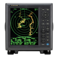
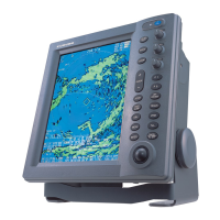
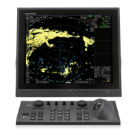
CHART RADAR
Model FCR-2139S-BB/2839S
(Product Name: MARINE RADAR)
SAFETY INSTRUCTIONS ........................i
SYSTEM CONFIGURATION ..................iii
EQUIPMENT LISTS.................................v
1. MOUNTING......................................1-1
1.1 Antenna Unit .......................................1-1
1.2 Monitor Unit.........................................1-8
1.3 Radar Control Unit/
Trackball Control Unit .........................1-8
1.4 Radar Processor Unit........................1-11
1.5 Processor Unit ..................................1-12
1.6 Sensor Adapter MC-3000S/3010A/
3020D/3030D (option).......................1-14
1.7 Intelligent Hub HUB-3000 (option)....1-15
1.8 Switching HUB HUB-100 (option).....1-16
2. WIRING............................................2-1
2.1 Interconnection ...................................2-1
2.2 Antenna Unit .......................................2-3
2.3 Radar Processor Unit..........................2-6
2.4 Processor Unit ..................................2-11
2.5 Monitor Unit.......................................2-22
2.6 Power Supply Unit ............................2-23
2.7 Sensor Adapters (option)..................2-24
2.8 Intelligent HUB HUB-3000 (option)...2-43
2.9 How to Extend the Control Unit Cable
(option)..............................................2-44
3. SETTING AND ADJUSTMENT .......3-1
3.1 How to Access the Radar Installation
Menu ...................................................3-1
3.2 How to Align the Heading ...................3-1
3.3 How to Adjust the Sweep Timing........3-2
3.4 How to Suppress Main Bang ..............3-2
3.5 Dual Radar Display.............................3-3
3.6 Other Settings.....................................3-6
3.7 Web Setting Menu ............................3-12
4. INSTALLING OPTIONAL
EQUIPMENT (for RADAR)..............4-1
4.1 Gyro Converter GC-10........................4-1
4.2 Junction Box .......................................4-9
5. INPUT/OUTPUT DATA ...................5-1
5.1 Radar Processor Unit..........................5-1
5.2 Processor Unit ....................................5-1
5.3 IEC 61162 Sentences .........................5-2
APPENDIX 1 JIS CABLE GUIDE.....AP-1
APPENDIX 2 ROD TERMINALS ......AP-2
APPENDIX 3
DIGITAL INTERFACE
....AP-8
PACKING LISTS ................................. A-1
OUTLINE DRAWINGS ........................ D-1
INTERCONNECTION DIAGRAMS ..... S-1