EasyManua.ls Logo

Furuno FCR-2829W User Manual

Furuno FCR-2829W
174 pages
To Next Page IconTo Next Page
Page #1 background imageLoading...
Page #1 background image
www.furuno.com
A
ll brand and product names are trademarks, registered trademarks or service marks of their respective holders.
Installation Manual
CHART RADAR
Model FCR-2829W/2839SW
(Product Name: MARINE RADAR)
SAFETY INSTRUCTIONS ........................i
SYSTEM CONFIGURATIONS................iii
EQUIPMENT LISTS................................vi
1. MOUNTING......................................1-1
1.1 Antenna Unit .......................................1-1
1.2 Monitor Unit.......................................1-12
1.3 Radar Control Unit/
Trackball Control Unit .......................1-12
1.4 Radar Processor Unit........................1-15
1.5 Processor Unit ..................................1-16
1.6 Sensor Adapter MC-3000S/3010A/
3020D/3030D (option) ......................1-18
1.7 Intelligent Hub HUB-3000 (option)....1-19
1.8 Switching HUB HUB-100 (option).....1-20
2. WIRING............................................2-1
2.1 Interconnection ...................................2-1
2.2 Antenna Unit .......................................2-3
2.3 Transceiver Unit..................................2-9
2.4 Radar Processor Unit........................2-14
2.5 Processor Unit ..................................2-18
2.6 Monitor Unit.......................................2-29
2.7 Sensor Adapters (option)..................2-30
2.8 Intelligent HUB HUB-3000 (option)...2-49
2.9 How to Extend the Control Unit Cable
(option)..............................................2-50
3. SETTING AND ADJUSTMENTS.....3-1
3.1 How to Access the Radar Installation
Menu...................................................3-1
3.2 How to Align the Heading ...................3-1
3.3 How to Adjust the Sweep Timing........3-2
3.4 How to Suppress Main Bang ..............3-2
3.5 Dual Radar Display.............................3-3
3.6 Other Settings.....................................3-6
3.7 Web Setting Menu ............................3-12
4. INSTALLING OPTIONAL
EQUIPMENT ....................................4-1
4.1 Gyro Converter GC-10........................4-1
4.2 Junction Box .......................................4-9
5. INPUT/OUTPUT DATA ...................5-1
5.1 Radar Processor Unit..........................5-1
5.2 Processor Unit ....................................5-1
5.3 IEC 61162 Sentences .........................5-2
APPENDIX 1 JIS CABLE GUIDE.....AP-1
APPENDIX 2 ROD TERMINALS ......AP-2
APPENDIX 3
DIGITAL INTERFACE
....AP-8
PACKING LISTS ................................. A-1
OUTLINE DRAWINGS ........................ D-1
INTERCONNECTION DIAGRAMS ..... S-1
Question and Answer IconNeed help?

Do you have a question about the Furuno FCR-2829W and is the answer not in the manual?

Furuno FCR-2829W Specifications

General IconGeneral
Power Output25 kW
Display TypeLCD
Resolution1920 x 1080 pixels
Frequency9.4 GHz (X-band)
Range72 nautical miles
Antenna Length8 feet
Power Supply24 V DC
WeightApprox. 15 kg

Summary

SAFETY INSTRUCTIONS

SYSTEM CONFIGURATIONS

EQUIPMENT LISTS

1. MOUNTING

1.1 Antenna Unit

Details on mounting considerations and assembly for the antenna unit.

1.2 Monitor Unit

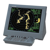
Guidance on selecting a location for the monitor unit installation.

1.3 Radar Control Unit/Trackball Control Unit

Mounting considerations and procedures for control units.

1.4 Radar Processor Unit

Mounting considerations and procedure for the radar processor unit.

1.5 Processor Unit

Mounting considerations and procedure for the processor unit.

1.6 Sensor Adapter MC-3000S/3010A/3020D/3030D (option)

Mounting considerations and procedure for sensor adapters.

1.7 Intelligent Hub HUB-3000 (option)

Mounting considerations and procedure for the intelligent hub.

1.8 Switching HUB HUB-100 (option)

Mounting considerations for the switching hub.

2. WIRING

2.1 Interconnection

Wiring considerations to minimize electrical interference.

2.2 Antenna Unit

Procedures for fabricating and connecting cables to the antenna unit.

2.3 Transceiver Unit

Procedures for fabricating and wiring cables for the transceiver unit.

2.4 Radar Processor Unit

Fabrication and connection procedures for power and signal cables.

2.5 Processor Unit

How to connect cables to terminals on the processor unit.

2.6 Monitor Unit

Wiring details for the monitor unit, including resolution and output settings.

2.7 Sensor Adapters (option)

Details on fabricating and attaching cables to sensor adapters.

2.8 Intelligent HUB HUB-3000 (option)

Instructions for fixing LAN cables to the intelligent hub.

2.9 How to Extend the Control Unit Cable (option)

Procedures for extending control unit cables for RCU-025 and RCU-026.

3. SETTING AND ADJUSTMENTS

3.1 How to Access the Radar Installation Menu

Steps to access the radar installation menu for adjustments.

3.2 How to Align the Heading

Procedure to align the antenna unit's heading for accurate display.

3.3 How to Adjust the Sweep Timing

Adjusting sweep timing to prevent echo display symptoms.

3.4 How to Suppress Main Bang

Steps to suppress main bang clutter at the radar screen center.

3.5 Dual Radar Display

How to enable/disable and configure dual radar display settings.

3.6 Other Settings

Describes menu items not previously covered, including Echo Adjust.

3.7 Web Setting Menu

Guidance on setting up the radar via a web browser.

4. INSTALLING OPTIONAL EQUIPMENT

4.1 Gyro Converter GC-10

Installation and setup of the Gyro Converter GC-10.

4.2 Junction Box

Requirements and mounting procedures for optional junction boxes.

5. INPUT/OUTPUT DATA

5.1 Radar Processor Unit

Details on input and output data for the radar processor unit.

5.2 Processor Unit

Details on input and output data for the processor unit.

5.3 IEC 61162 Sentences

Explanation of IEC 61162 sentences for digital interface.

APPENDIX 1 JIS CABLE GUIDE

APPENDIX 2 ROD TERMINALS

APPENDIX 3 DIGITAL INTERFACE

Related product manuals