2. WIRING
2-30
How to open the [INSTALLATION SETTING] menu
Turn off the monitor unit. While you hold the DISP key, press the BRILL key to turn on
the monitor unit. Press and hold the DISP key for more than five seconds.
Note: When the [DVI PWR SYNC] slide switch is ON, turn on the connected external
equipment while you press the DISP key to turn on the monitor unit.
2.7 Sensor Adapters (option)
Maximum eight MC-3000S can be connected to a sensor network (for the redundant
connection: 16). The MC-3000S (serial input/output, IEC61162-2/1, 4ch) can connect
max. 10 sensor adapters using the MC1.5-W cables. The maximum number of MC-
3010A units is five.
When fabricating the MC1.5-W cables, use the lot terminal (ferrule type, supplied) to
maintain performance. This fabrication requires the optional crimping tool (type:
CRIMPFOX 10S). For the relations between the connectors and rod terminals, see
page AP-2. Also, the stickers attached on the reverse side of the covers show the de-
tailed connections.
Attache the cables to the applicable pins.
Use the ferrule-type terminals (supplied) to connect the cables to the terminals in the
sensor adapters. This connection requires a crimping tool (CRIMPFOX10S, option).
Note 1: Use the MC1.5-W cable between the sensor adapters.
Note 2: The total length of the MC1.5-W cables should be less than 6 m to prevent
malfunction.
Pin No. Cable color Signal
1 Red 24V_OUT or 24V_IN
2Black 24V_GND
3 White MODBUS-A
4 Blue MODBUS-B
5Gray GND
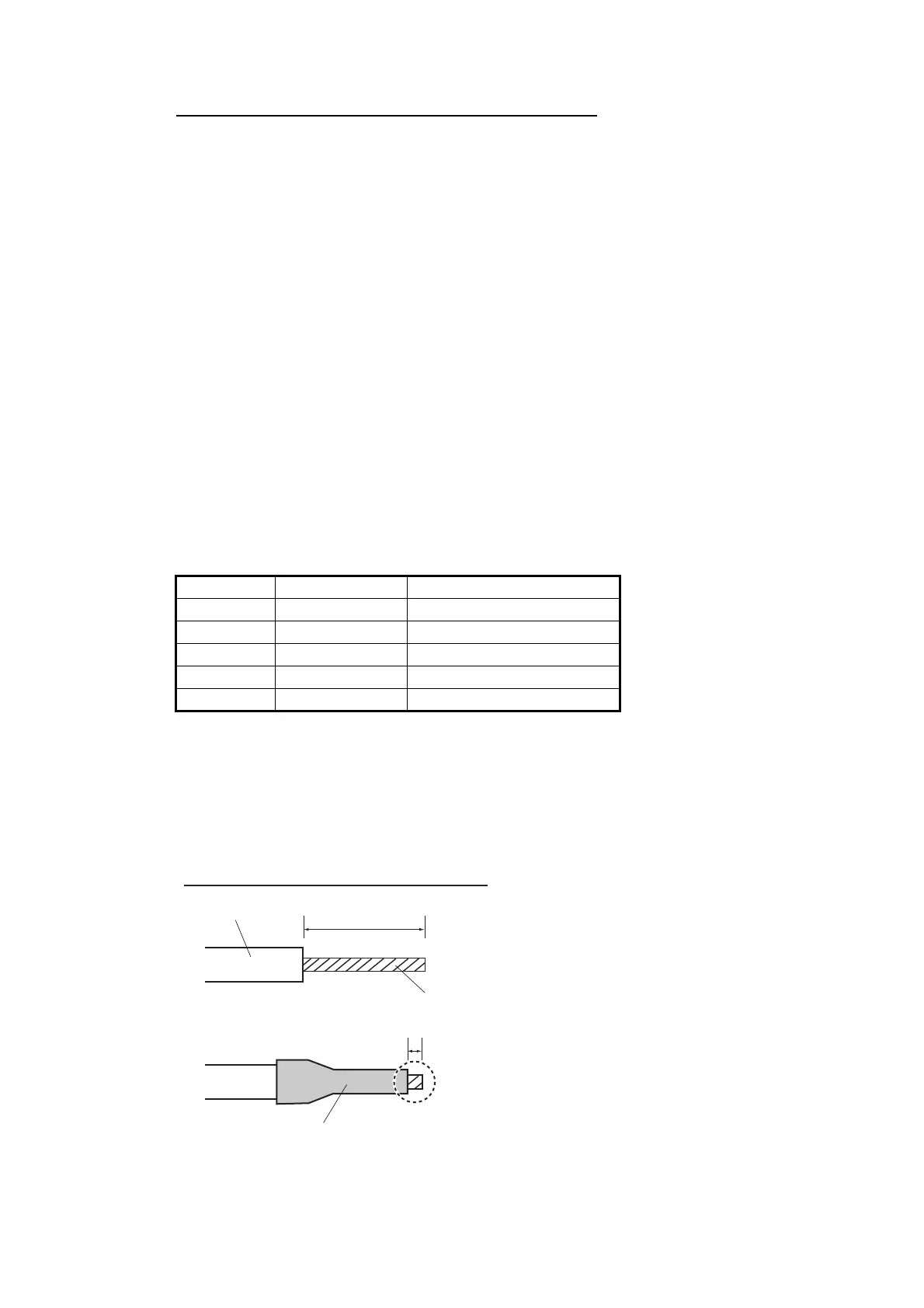
Rod terminal (ferrule type):
After attaching the rod terminal, use the optional crimping tool CRIMPFOX
10S to crimp.
6mm
0.5 to 1 mm
How to attach the rod terminal (ferrule type)
Core
Vinyl sheath