8
Cable Fabrication, Connector Attachment
Antenna cable connector at the Communication unit
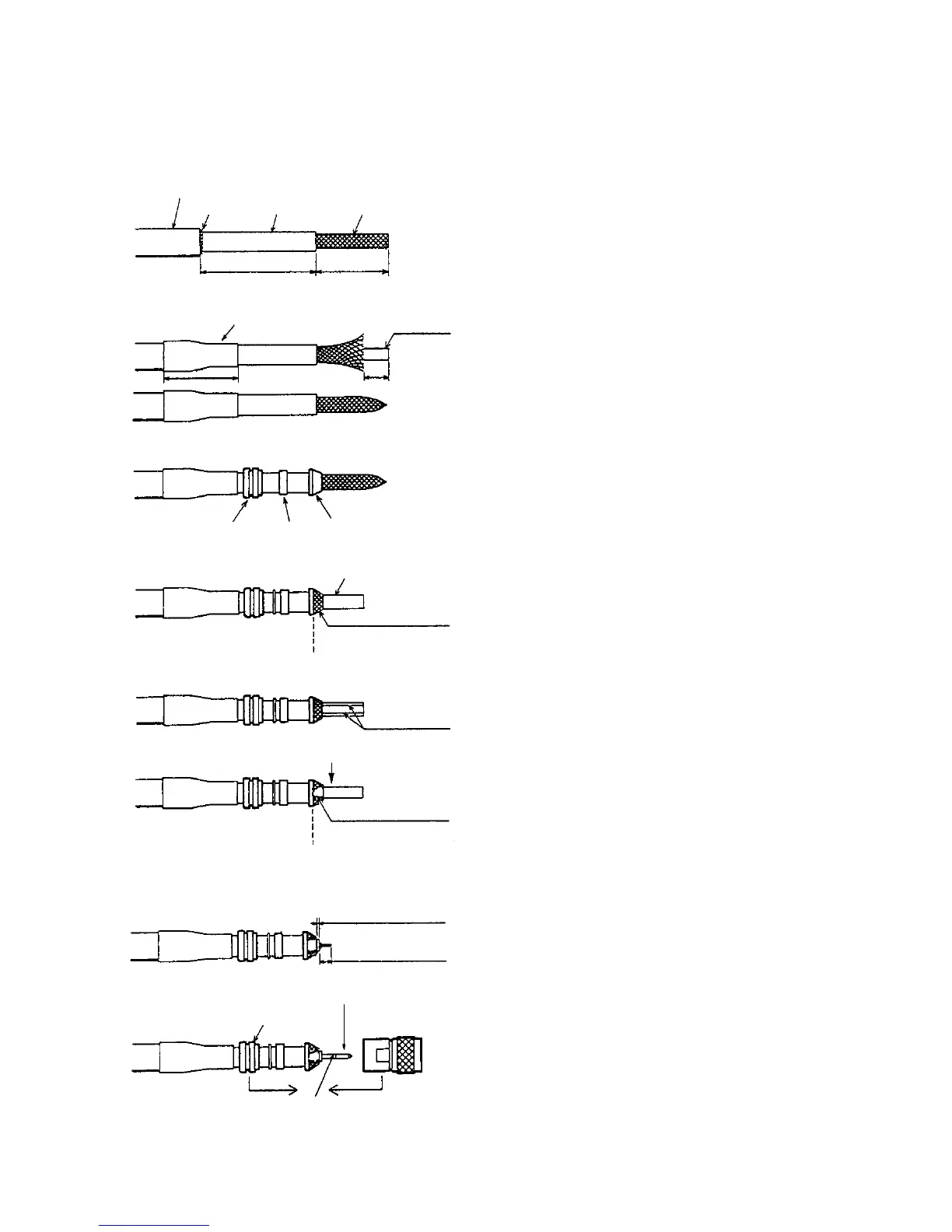
How to attach the antenna cable connector N-P-5DFB/N-P-8DFB
Outer Sheath
Armor
Dimensions in millimeters.
Inner Sheath Shield
50 30
Cover with heat-shrink tubing and heat.
10
30
Clamp
Nut
Gasket
(reddish
brown)
Clamp
Aluminum Foil
Trim shield here.
Insulator
Trim aluminum
tape foil here.
1
5
Clamp Nut
Pin
Shell
Solder through
the hole.
Remove outer sheath and armor by the
dimensions shown left.
Expose inner sheath and shield by the
dimensions shown left.
Remove insulator and core by 10 mm.
Twist shield end.
Slip on clamp nut, gasket and clamp as shown
left.
Fold back shield over clamp and trim.
Cut aluminum foil at four places, 90˚ from one
another.
Fold back aluminum tape foil onto shield and trim.
Expose the insulator by 1 mm.
Expose the core by 5 mm.
Slip the pin onto the conductor. Solder them
together through the hole on the pin.
Insert the pin into the shell. Screw the clamp
nut into the shell.
(Tighten by turning the clamp nut. Do not
tighten by turning the shell.)
Figure 4-2 How to attach antenna cable connector N-P-5DFB/N-P-8-DFB
 Loading...