11
5. INSTALLATION OF GPS BOARD
ASSEMBLY (OPTION)
A GPS receiver board can be installed in the
Communication Unit IC-212. There are two
kind of GPS board assemblies: OP16-16-1 and
OP16-16-2. The former is fitted at factory; the
latter in the field. Here, installation of the latter
is explained.
Table 5-1 Contents of GPS board
assembly OP16-16-2
*1) Both are equivalent
*2) For GN-74 NNCC-N-E
*3) For GN-7707
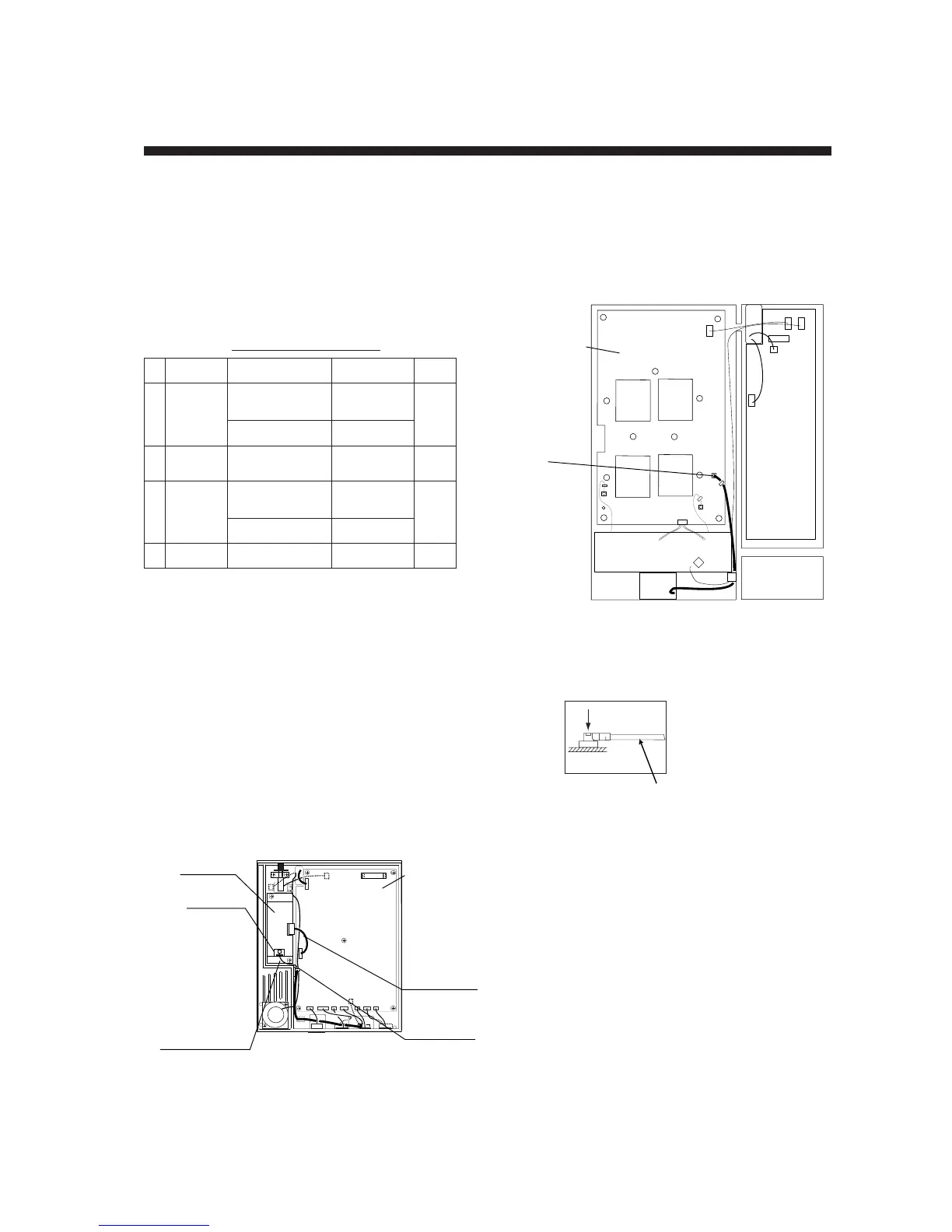
1. Unfasten twelve screws to remove top and
bottom covers on the communication unit.
2. Fix the GPS pcb assy. to the bottom of the
unit with M3x6 screws.
3. Fix the cable assy. 51065-0700-PHR-8-L50
between J2 of the GPS pcb assy. and J8 of
the CPU pcb as follows.
J9
J8
J1 J2
J2
J1
J3
J4
J5
J6
J7
Cable
assembly
51065-
0700-PHR
-8-L50
CPU pcb
Cable
assembly
S.FL2-2LPO.
7DWHA (400)
NOTE 1
GPS pcb
Front side
Rear side
Mini clamp
Figure 5-1 Communication unit, bottom view
(bottom cover removed)
4. Fix the cable assy. S.FL2-2LP0.7DWHA
(400) between J1 of the GPS pcb and J4 of
the RFCONV pcb and secure it with three
mini-clamps. Refer to Figures 5-1 and 5-2.
J5
J2
J4
J4
NOTE1
RFCONV
pcb
Front side
Figure 5-2 Communication unit, top view
(top cover removed)
NOTE1: Insert connectors vertically.
Cable assembly
emaNepyT.oNedoCytQ
1
bcpSPG
.yssa
-CCNN47-NG
E-N1*
028-244-400
1
1*7077-NG804-141-000
2
elbaC
.yssa
-D7.0PL2-2LF.S
)004(AHW
643-041-0001
3
elbaC
.yssa
-0070-56015
05L-8-RHP2*
606-631-000
1
3*6930S61154-241-000
4wercS6x3M304-188-0002
 Loading...