4-16
5. Connect the XH connector assembly (supplied) between J501 (13P) on the
RGB BUFF Board and J108 (13P) on the SPU Board.
6. Bind XH connector with coach clip (supplied).
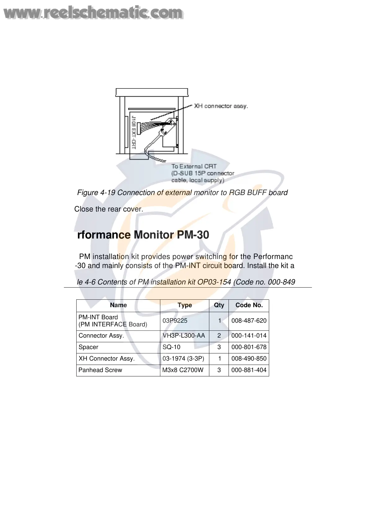
7. Connect a monitor cable (D-SUB15P connector cable, local supply) between
the RGB BUFF Board and the external CRT.
Figure 4-19 Connection of external monitor to RGB BUFF board
8. Close the rear cover.
4.6 Performance Monitor PM-30
The PM installation kit provides power switching for the Performance Monitor
PM-30 and mainly consists of the PM-INT circuit board. Install the kit as follows:
Table 4-6 Contents of PM installation kit OP03-154 (Code no. 000-849-083)
Name Type Qty Code No.
PM-INT Board
(PM INTERFACE Board)
03P9225 1 008-487-620
Connector Assy. VH3P-L300-AA 2 000-141-014
Spacer SQ-10 3 000-801-678
XH Connector Assy. 03-1974 (3-3P) 1 008-490-850
Panhead Screw M3x8 C2700W 3 000-881-404
1. Unfasten eight screws to remove the cover.
2. Remove the top cover.
3. Attach three spacers to the bottom of the GYRO PROCESSOR Board
(64P1106A). Fasten the PM-INT Board (03P9225) to the spacers with panhead
screws (supplied).
4. Solder the VH connector assy. (supplied) to the power line (100/220 VAC) and
connect the line to J402 on the PM-INT Board.
www.reelschematic.com
www.reelschematic.com
 Loading...