55
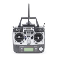
Charging jack -Charging jack - Port for charging the transmitter batteries with the included battery charger.
On-off switchOn-off switch
DATA INPUT lever -DATA INPUT lever - Used to change the values of the various functions displayed on the LCD screen.
Liquid-crystal display screenLiquid-crystal display screen (LCD) - Displays programming modes and values entered.
MODE key -MODE key - Used to scroll through and display the seven different functions.
SELECT key -SELECT key - Used to display the values for the current function.
Throttle/rudder control stick -
Throttle/rudder control stick - Operates the servos connected to channel 3 (throttle) and channel 4 (rudder) in the receiver.
Trainer switch -
Trainer switch - Operates the trainer functions. To operate as a trainer switch the transmitter must be connected to another
transmitter via. a trainer cord (available separately).
Antenna -
Antenna - Radiates signals to the receiver. Never fly a model without fully extending the antenna or you may create
interference to other modelers and decrease operational signal range of the transmitter. The antenna may be removed and
replaced with another in case it is inadvertently broken.
RADIO INSTALLATIONRADIO INSTALLATION
Follow these guidelines to properly mount the servos, receiver and battery.
•• Make certain the alignment tabalignment tab on the battery, switch and servo connectors is oriented correctly and “keys” into the
corresponding notch in the receiver or connectors before plugging them in. When unplugging connectors, never pull on the
wires. Always pull on the plastic connector instead.
•• If any servo wires are not long enough to reach the receiver, servo extension wires (available separately) may be used.
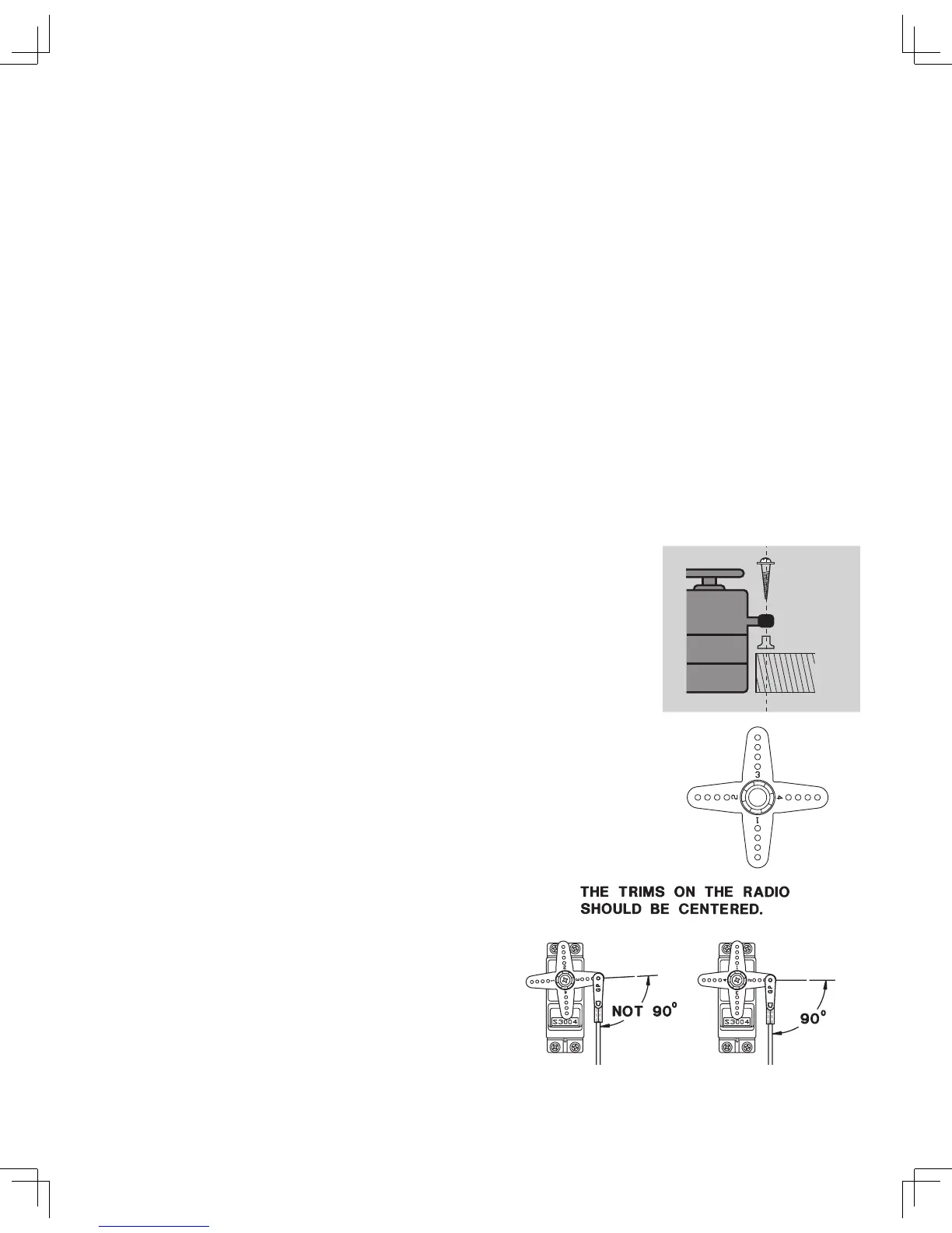
•• Always mount the servos with the supplied rubber grommetsrubber grommets. Do not over tighten the
screws. No part of the servo casing should contact the mounting rails, servo tray or any
other part of the airplane structure. Otherwise, vibration will be transmitted to the servo
causing premature wear and/or servo failure.
•• Note the small numbers (1, 2, 3, 4) molded into each arm on the Futaba 4-arm servo arms.
The numbers indicate how many degrees each arm is
“off” from 90 degrees to correct for
minute manufacturing deviations from servo to servo.
•• To center the servos, connect them to the receiver and turn on
the tr an s mi tt e r and r ec e iv er. C e nt e r the t ri ms on t he
transmitter, then find the arm that will be perpendicular to the
pushrod when placed on the servo.
Rubber
grommet
Servo