Ni-Cd battery pack
Charging jack
Battery cover
Battery connector location
Trainer connector
Switch/Knob Airplane (ACRO) Helicopter (HELI)
A or H Tx.
S
WITCH A elevator dual rate elevator dual rate
Switch B rudder dual rate rudder dual rate
up = ELE-FLP on
down = AIRBRAKE
S
WITCH D aileron dual rate aileron dual rate
Switch E
OR G* landing gear/ch 5 throttle hold
Switch F
OR H* snap roll/trainer trainer
S
WITCH G OR E* idle-up 1 and 2,
ch5/OFFSET/GYRO
K
NOB VR flap/ch 6 HOVERING PIT
(flap trim if FLAPERON on)
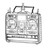
* On the 7CA (mode 2) transmitters, the Top Left Switches are spring-loaded switch and 2-position switch. On the 7CA (mode 1) and 7CH
transmitters, the Top Left Switch is a 3-position with the spring loaded switch on the top right.
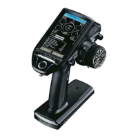
NOTE: If you need to remove or replace the transmitter battery, do not pull on its wires to remove it. Instead,
gently pull on the connector's plastic housing where it plugs into the transmitter.
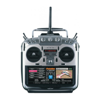
SWITCH ASSIGNMENT TABLE
•
The factory default functions activated by the switches and knobs for a Mode 2 transmitter are shown below.
•
Most 7C functions may be reassigned to non-default positions quickly and easily.
•
Basic control assignments of channels 5 & 7 are quickly adjustable in PARA (see p. 28). For example, the channel 5
servo, which defaults to S
WITCH E for retract use, can easily be unassigned (NULL) to allow for easy use as a second
rudder servo in a mix, or to a dial for bomb door or other control.
•
Note that most functions need to be activated in the programming to operate.
•
Mode 1 transmitter functions are similar but reverse certain switch commands. Always check that you have the desired
switch assignment for each function during set up.
LED
13
Green Red Status
Solid Solid Initializing (When Power Up)
Alternate blink Check RF condition nearby
Solid Off RF power on
Solid Blink
RF power on (Power reduced to perform the
range check function.)
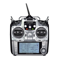
LED indication
When the transmitter is powered up, the LEDs on
the rear of the transmitter will begin to glow or
blink accordingly. The chart below provides you
with an easy reference as to the meaning of the
LEDs.
on
 Loading...