25
ڀ ŪŲŃƗƒŃŷŤťůŨŃŲũŃŦŲűŷŨűŷŶ
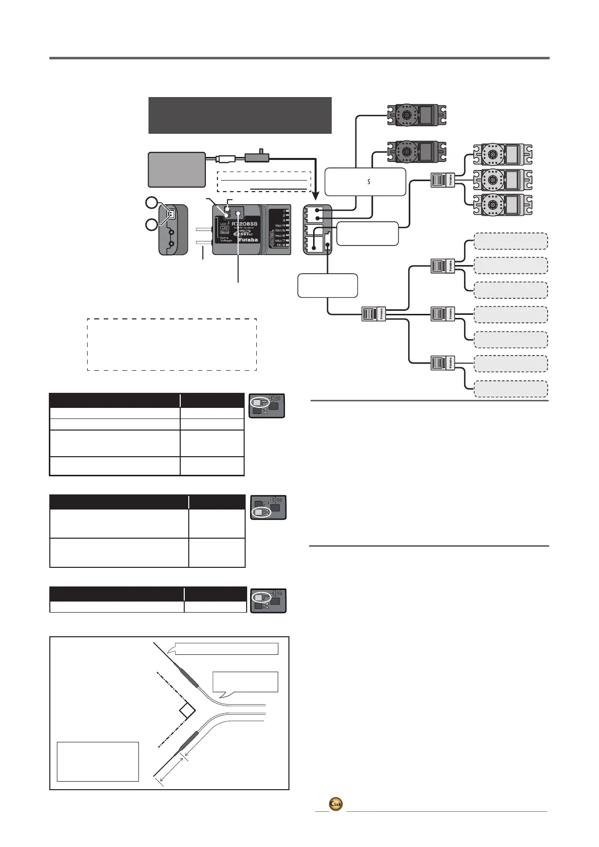
ŵƈƆƈƌƙƈƕŃƑƒƐƈƑƆƏƄƗƘƕƈ
6HUYRIRUFRQYHQWLRQDO
V\VWHP
0RGH/('
/LQN/('
$QWHQQD
0RGHVZLWFK
([WUD9ROWDJH3RUW
,WLVQRWXVHGIRUDOLQN
,WFRQQHFWVZLWKWKHEDWWHU\
IRUSRZHUHWF
([WHUQDOYROWDJHLQSXW
FDEOHRIDQRSWLRQLVXVHG
7KHYROWDJHRIWKHEDWWHU\
FDQEHGLVSOD\HGZLWKD
WUDQVPLWWHU
6%866HUYR
6%86*\UR
+8%
+8%
+8%+8%
+8%
R7208SB
%DWWHU\
ع 9
6ZLWFK
7KHEDWWHU\FRQQHFWHGWR
DQ\HPSW\SRUW
7HPSHUDWXUH
6HQVRU
9ROWDJH
6HQVRU
&XUUHQW
6HQVRU
530
6HQVRU
$OWLWXGH
6HQVRU
$LUVSHHG
6HQVRU
6%867RRO
6%86SRUW
6%86ك
6%86SRUW
6%ك
&KDQQHORXWSXW
&KDQQHORXWSXW
+
−
,IDOORIWKHUHFHLYHUVLQSXWRXWSXWSRUWVDUHRFFXSLHG
E\VHUYRVHWFXVHDQRSWLRQDOWHUPLQDOER[HWFDQG
FRQQHFWWKHEDWWHU\ZKLOHSD\LQJDWWHQWLRQWRWKH
VHUYRVFXUUHQWFRQVXPSWLRQ
(Typicalinstallation)
The R7208SB has a port switching
The R7208SB has a port switching
function. If SB2/4 to SB2/7 ports are
function. If SB2/4 to SB2/7 ports are
also set to S.BUS2, sensors can be
also set to S.BUS2, sensors can be
connected.
InDualRXLinkMode
InFASSTest12CHTelemetryOFFMode
Status MODELED
Externalreceiverisreceivingerroror
notconnected.
S.BUSsignalnotreceived
RedSolid
S.BUSsignalreceptionfromexternal
receiver
(alsoreceivedbyexternalreceiver)
GreenSolid
Status LINKLED
Start OrangeSolid
LEDIndication
Status LINKLED
Nosignalreception RedSolid
Receivingsignals GreenSolid
Waitingforlink
Start → 2second
later → Red
Blink(3second)
Unrecoverableerror(EEPROM,etc.)
RedGreen
Alternateblink
Antenna
installation
Donotbendtheantennapart
Antennapart
Gentlybendthe
coaxialcablepart.
Coaxialcable
Antennashouldbe
securedsothatit
cannotmovearoundor
backinsideofaircraft.
90°
ŶőťŸŶŕŃŃŃؙؙŃŃŃŃŃŃŃŃŃŃŃŃŃŃŃŃŃŃŃŃŃŃŃŃŃŃŃŃŃŃŃŃŃŃŃŃŃŃŃ
S.BUS2 extends S.BUS and supports bidirectional
communication. Sensors are connected to the
S.BUS2 port.
ŃŤƑƗƈƑƑƄŃƌƑƖƗƕƘƆƗƌƒƑƖ
1.
The two antennas must be kept as straight as possible.
Otherwise it will reduce the effective range.
2.
The two antennas should be placed at 90 degrees to
each other.
This is not a critical figure, but the most important
thing is to keep the antennas away from each other as
much as possible.
Larger models can have large metal objects that can
attenuate the RF signal. In this case the antennas
should be placed at both sides of the model. Then
the best RF signal condition is obtained at any flying
attitude.
3.
The antennas must be kept away from conductive
materials, such as metal, carbon and fuel tank by at
least a half inch. The coaxial part of the antennas does
not need to follow these guidelines, but do not bend it
in a tight radius.
4.
Keep the antennas away from the motor, ESC, and other
noise sources as much as possible.
*S.BUS compatible servos and gyros cannot be used with the
S.BUS2 port. S.BUS compatible servos and gyros are used
with the S.BUS port.
*When using FASSTest26ch,
S.BUS can only be used for 18ch (1-16ch+DG1,2).
S.BUS2 can use 26ch (1-24ch+DG1,2).
 Loading...