8
RELAYS
PIN SYMBOL DESCRIPTION
C1 –R2 Solid State Relay 2 (–)
C2 +R2 Solid State Relay 2 (+)
C3 –R1 Solid State Relay 1 (–)
C4 +R1 Solid State Relay 1 (+)
ANALOG OUTPUT
PIN SYMBOL DESCRIPTION
D1 –VOUT Voltage Output (–)
D2 +VOUT Voltage Output (+)
D3 G Ground (current)
D4 IOUT Current Output
Ground (G) connections can be used to
connect a cable shield.
Strain Gauge Input is for sensors with a
mV/V output level.
Green screw terminals can be
removed to allow easy access to
connect the wires.
TIPS FOR WIRING
Wiring Layout (continued)
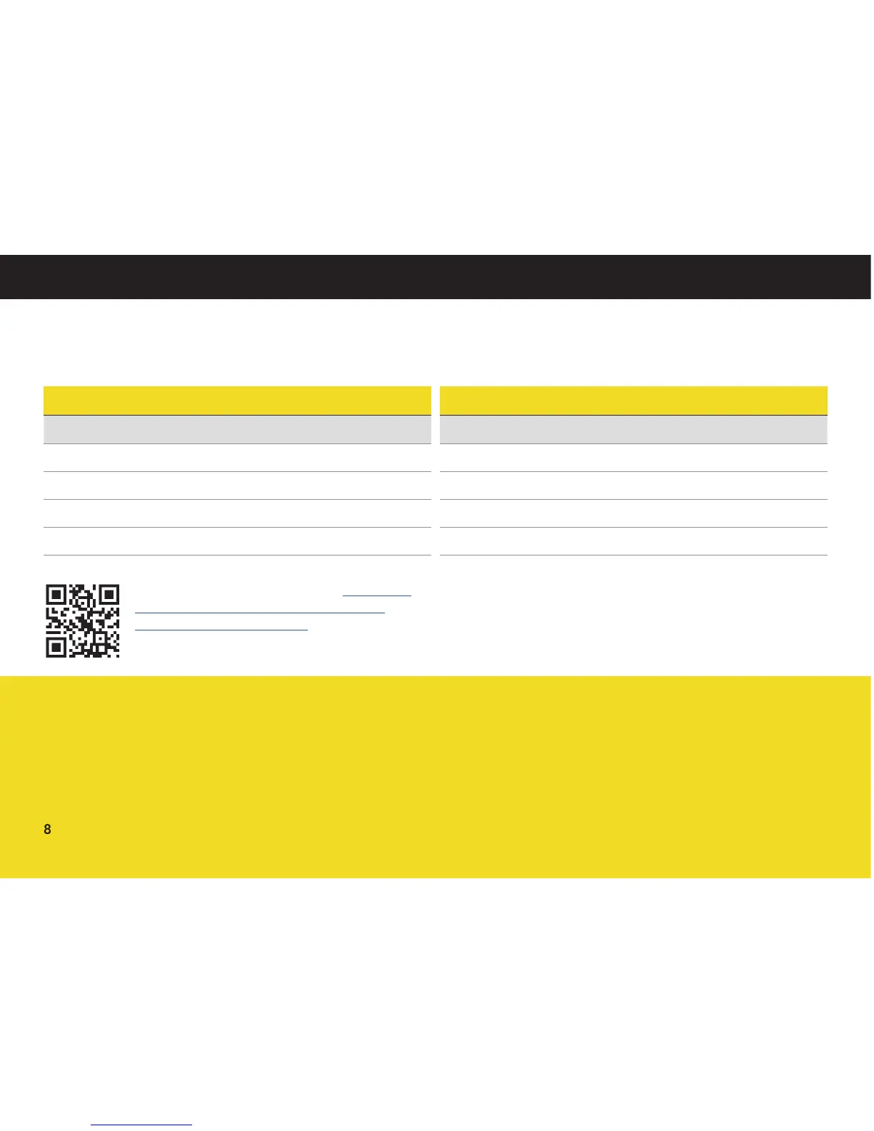
IPM650 Wiring Connection Examples: http://www.
futek.com/files/Pdf/Manuals_and_Technical_
Documents/IPM650Wiring.pdf