Do you have a question about the Futek IPM650 and is the answer not in the manual?
Check all parts for damage during transit. Contact FUTEK if damaged.
Store device between 0°C and +70°C in a dry environment.
Lists included accessories like power adapter and plugs.
Details the IPM650's capabilities, accuracy, and specifications.
Highlights key features and compliance standards.
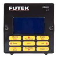
Provides a visual overview of the IPM650's front panel and components.
View stored sensor profiles and their active status.
Display details of a selected channel, including serial and sensor type.
Procedure to create and configure a new sensor channel.
Modify settings for existing sensor channels.
Save modifications made to sensor profiles.
Remove unwanted sensor channels from memory.
Configure the number of digits displayed on the screen.
Choose the active channel for operation.
Set up averaging for signal filtering.
Select the data acquisition rate.
Configure peak and valley capture modes.
Enable/disable automatic reset of peak/valley values.
Set alarm behavior to latched or non-latched.
Enable or disable system and relay alarms.
Set the speed for data logging.
Define the logging duration in seconds.
Start or stop the data logging process.
Configure termination characters for ASCII output.
Configure the normally open/closed state of alarm relay 1.
Configure the normally open/closed state of alarm relay 2.
Select uni-polar or bi-polar voltage output.
Select the output current range (e.g., 0-20 mA).
Set current output for uni- or bi-directional operation.
Enable or disable the USB output functionality.
Enable or disable the ASCII data output.
Enable or disable the relay 1 output.
Enable or disable the relay 2 output.
Enable or disable the voltage output feature.
Enable or disable the current output feature.
Enable or disable the power output supply.
Enable or disable the bridge sensor input.
Enable or disable the voltage sensor input.
Enable or disable the current sensor input.
Adjust the LCD display contrast level.
Adjust the LCD display brightness level.
Configure the automatic LCD screen turn-off timer.
Lock settings to prevent unauthorized changes.
Unlock settings with the correct password.
Update the device's password.
Display information about a connected TEDS device.
Access and view TEDS data pages.
Load a profile from TEDS data and perform auto-calibration.
Enable/disable automatic TEDS device detection on power-up.
Perform internal or external diagnostic tests.
Explains the concept and purpose of TEDS technology.
| IP Rating | IP40 |
|---|---|
| Operating Temperature | 0°C to 60°C [32°F to 140°F] |
| Power Supply | 12 VDC |
| Material | Stainless Steel |
| Safe Overload | 150% of Rated Output |