EasyManua.ls Logo

Futek IPM650 - Connector & Wiring Diagram

Futek IPM650
121 pages
Print Icon
To Next Page IconTo Next Page
To Previous Page IconTo Previous Page
Loading...
- 8 -
10 Thomas, Irvine, CA 92618 USA
Tel: (949) 465-0900
Fax: (949) 465-0905
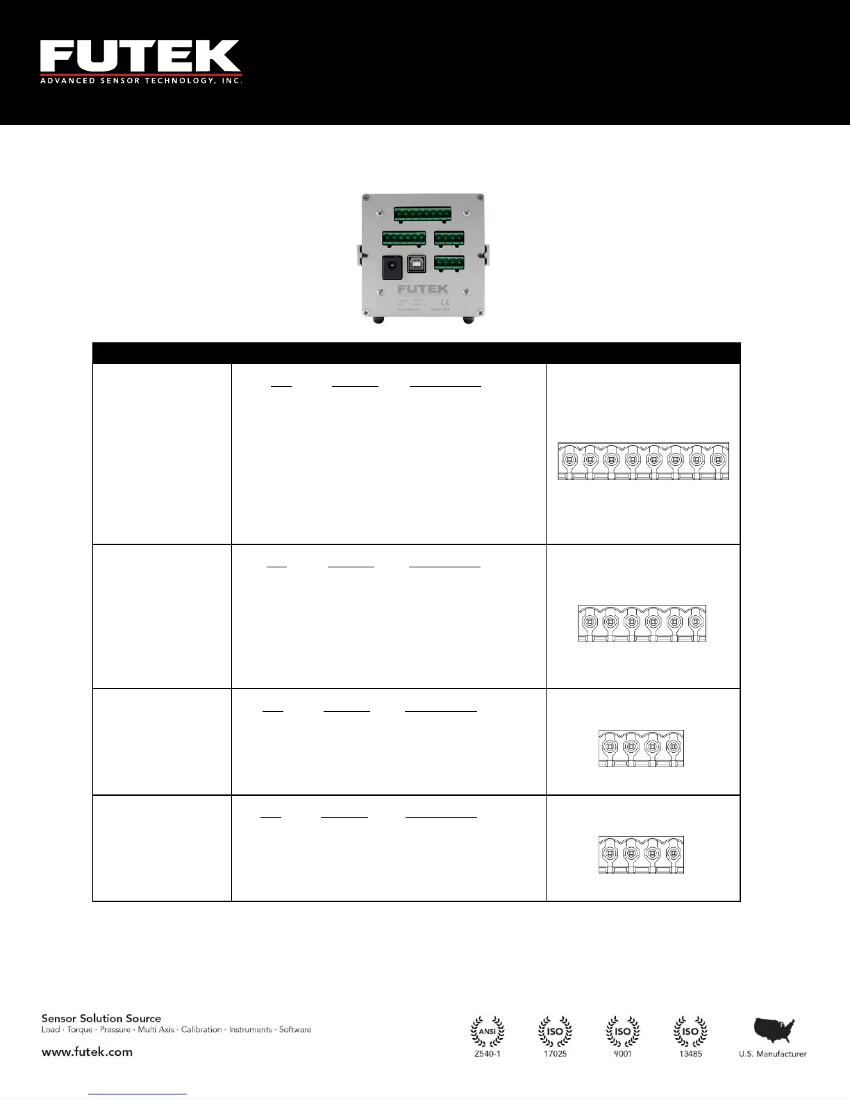
5 Connector & Wiring Diagram
* Sensor cable shield should only be grounded on one end, either the sensor side or the instrument side, to avoid
potential ground loops. If connected on instrument side use the following directions: Connect shield to pin 1 or pin
2 of Amplified Input if sensor is amplified. Connect shield to pin 1 of Strain Gauge Input if sensor is strain gauge.
Connectors
Description
Diagram
Amplified Input
Pin
Symbol
1
G
2
G
3
24V OUT
4
5V OUT
5
-V
6
+V
7
PLEAD
8
PLAG
1 2 3 4 5 6 7 8
Strain Gauge
Input
Pin
Symbol
Description
1
G
Ground/Shield*
2
TEDS
TEDS Data
3
-S
-Signal
4
+S
+Signal
5
-E
-Excitation
6
+E
+Excitation
1 2 3 4 5 6
Relays
Pin
Symbol
Description
1
-R2
Solid state relay 2
2
+R2
Solid state relay 2
3
-R1
Solid state relay 1
4
+R1
Solid state relay 1
1 2 3 4
Analog Output
Pin
Symbol
Description
1
-VOUT
Voltage output (-)
2
+VOUT
Voltage output (-)
3
G
Ground (current)
4
IOUT
Current output
1 2 3 4

Table of Contents

Other manuals for Futek IPM650

Related product manuals