10
For a SWITCH modifier you should enter Amp settings programming function and set states of lines
SW1 to SW4 to achieve the desired amp settings. SWITCH modifier recalls desired amp settings so to
switch e.g. between two channels it is needed to program two footswitches as SWITCH modifiers.
For a MIDI modifier you should apply the same procedure considering that you can program footswitch to
control one of MIDI devices (or more) and by Control Change commands one of the function of selected
MIDI device. This is possible by using unused function (not transmitting a given command) and toggle
function (for Control Change commands).
Tap tempo
The GSC enables to send tempo to a MIDI 1 device. To achieve it the tap tempo function (in settings at
footswitch No. 5) should be set to tt1. After selecting a preset by a footswitch next pressing of this foot-
switch effects in transmitting the CC command (Control Change) with the parameter 80 and its value
toggled between 0 and 127. If this footswitch is a LOOP modifier then this command is not transmitted.
The rest of modifiers transmit commands. It is recommended to tap tempo by pressing such a footswitch
two or three times. It is possible to program a footswitch to solely be used for tapping tempo. In such a
case this footswitch should be programmed as a MIDI modifier without transmitting program numbers
(unused). You should remember that in such a case to tap tempo you need to press this footswitch three
times. If you need to send to one device Control Change commands and tap tempo set the same trans-
mission channel for the MIDI 1 and MIDI 3 devices.
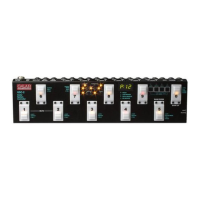
Settings
Settings parameters have been divided between LOOP and SWITCH buttons. The setting parameters of
MIDI channels transmission are assigned to the MIDI buttons. Factory settings in the tables below are
bolded.
LOOP button settings
a) Memory access lock switch to LOCK position (pressed, LOCK indicator lit).
b) Press and hold LOOP button then memory access lock switch to UNLOCK position (LOCK
indicator stops lit). The LOOP indicator starts to blink and SWITCH, MIDI 1 and MIDI 2 indicators
start to light. Text SP1 will appear on display.
c) First pressing footswitches will effect in displaying status of particular settings, the next pressing
effect in changing the status of particular settings.
cb0
change bank mode 0 – constantly selected bank No. 0
cb1
change bank mode 1 –changing the bank by pressing and holding (over 1
second) footswitches;
cb2
change bank mode 2 – changing the bank by using BANK UP footswitch
to increase or BANK DOWN footswitch to decrease a bank number
1
cb3
change bank mode 3 – changing the bank by using BANK UP footswitch
to increase or BANK DOWN footswitch to decrease a bank number with
immediate recalling of the preset (for firmware 2.20 and higher).
uP0 wah-pad 0 – wah-pad not active
uP1
wah-pad 1 – WP type wah-pad connected
2
uP2
wah-pad 2 – TBWP type wah-pad connected
uL1 wah loop 1 – wah-pad connected to the LOOP1 loop
…
3
uL6
wah loop 6 – wah-pad connected to the LOOP6 loop.
This setting is only important for adding to preset a wah-wah effect mode (Add).