12
MIDI channels setting
Controller enables to control (by a Program Change command) three MIDI devices marked as MIDI 1, MIDI 2
and MIDI 3. To set the connection between desired device at the GSC and connected device should be set
the same MIDI channel.
MIDI 1 device channels setting:
a) Memory access lock switch to LOCK position (pressed, LOCK indicator lit).
b) Press and hold MIDI 1 button and while it is pressed switch memory access lock to UNLOCK
position (LOCK indicator stops to light, MIDI 1 indicator starts to blink). The actually used channel
No. will appear on display.
c) Enter the desired channel No. by footswitches.
d) Press the MIDI 1 button to save settings (text Stored confirms saving).
In case of necessity of escaping without saving while in the point c) should be pressed LOOP or SWITCH
button.
For MIDI 2 device do it in similar way and for MIDI 3 device the MIDI 1 and MIDI 2 buttons should be pres-
sed simultaneously.
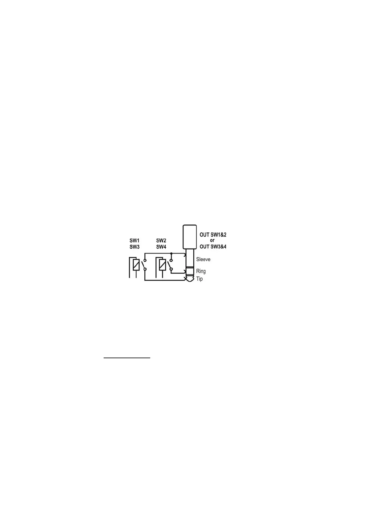
Amp’s control connecting
The SW1 to SW4 outputs are used to control an amp by its footswitch input. Depending on features of your
amp they can be used for switching channels, switching on/off reverb or effects loop, BOOST function or
other.
SW1&2 and SW3&4 outputs’ circuit diagram is shown below.
SW1 to SW4 lit indicators mean short-cutting of the adequate relay’s contacts (latching type). This circuit is
separated from the rest of the controller’s circuits. It is recommended to use connectors with plastic shielding
to avoid incidental connection with a signal grounding. Lot of amps are equipped with such type of a foot-
switch input so if your amp is equipped with footswitch input connector you should contact your dealer or
the manufacturer of your amp to settle if such type of connection is possible to apply. Depending on an
amp model this connection have to be done using mono or stereo Jack/Jack cable, Y type cable (stereo
Jack – 2 x mono Jack) or using a cable or an adapter offered by G LAB. The actual list of available cables
and adapters you’ll find at www.glab.com.pl
G LAB WP Wah-Pad connecting
The wah-pad enables switching on a wah-wah effect by placing a foot on it and switching off a wah-wah
effect by removing a foot. The wah-pad should be placed beneath a wah-wah effect and the wah-pad’s
connector should be plugged into WAH-PAD connector. A wah-wah effect’s input and output should be con-
nected to LOOP1 up to LOOP6 connectors. Wah-pad settings are described at “LOOP button settings”. At
LOOP button settings footswitch No. 2 set uP1 and set the loop No. to which your wah-wah effect is
connected for footswitch No. 3.
Depending on WAH PAD MODE parameter the wah-pad enables to activate in any preset of given bank
the loop your wah-wah effect is connected (“adding a wah-wah” mode) or to switch to preset No. 9 in given
bank (“changing preset” mode). To program the WAH PAD MODE parameter press SWITCH button (“Amp
settings programming” function) and use footswitch No. 5. Add means “adding a wah-wah” mode, Pr9 means
“changing preset” mode. In case of using “changing preset” mode you need to set at a loop to which a wah-
wah effect is connected in a No. 9 preset of a given bank. Such solution enables to simultaneously control