EasyManua.ls Logo

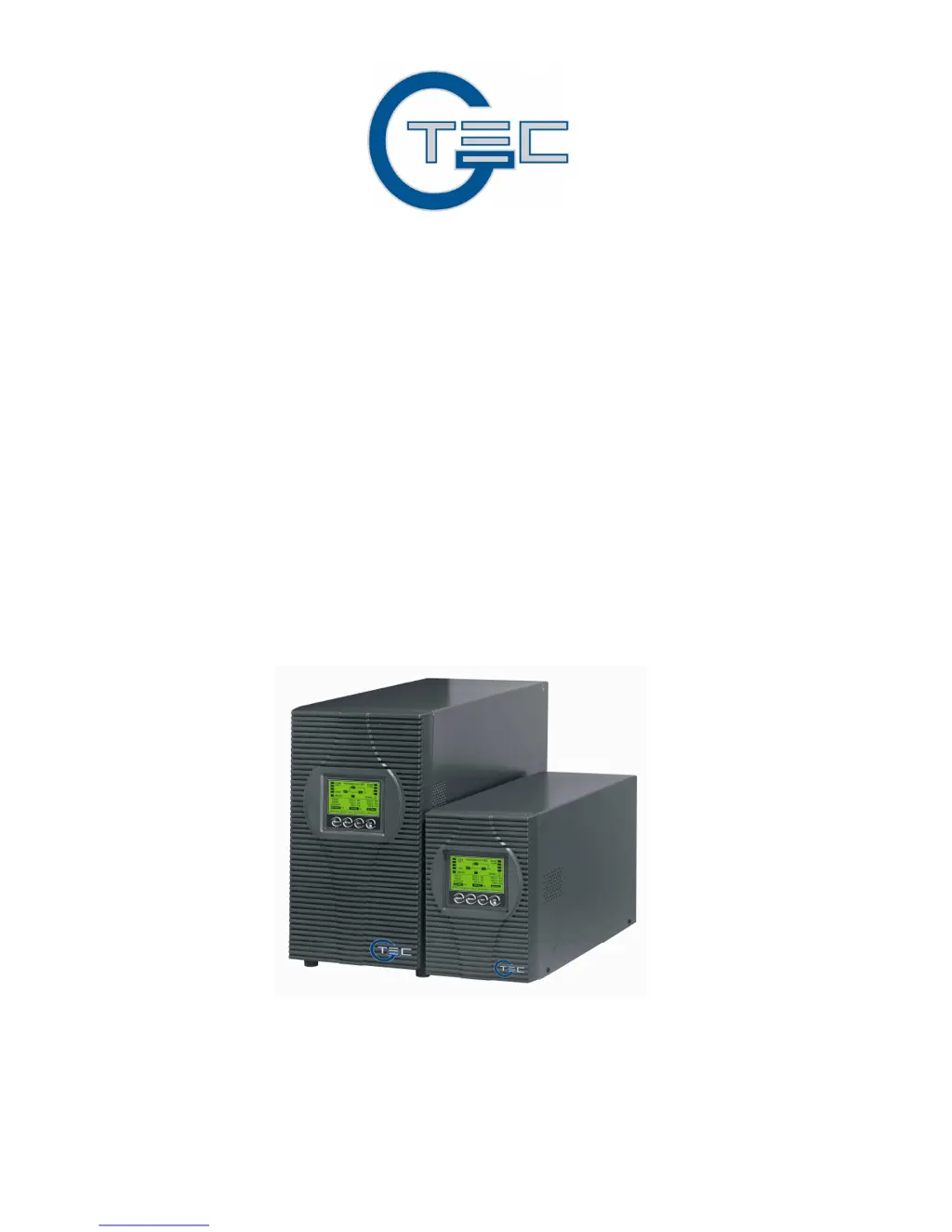
G-Tec ZP120LCD - User Manual

G-Tec ZP120LCD
69 pages
Print Icon
To Next Page IconTo Next Page
Loading...
-1-
USER’S MANUAL
MANUALE UTENTE
For Models ZP120LCD
1~3KVA
Uninterruptible Power System

Table of Contents

Questions and Answers

  • S
    Sarah WagnerAug 13, 2025
    What to do if G-Tec ZP120LCD emergency supply period is shorter than expected?
    • S
      Sheila RussellAug 14, 2025
      If the emergency supply period of your G-Tec UPS is shorter than expected, it may be because the batteries are not fully charged or are defective. Charge the batteries for at least 1 to 2 hours and then check the capacity. If the problem persists, it indicates a deeper issue.
  • R
    ryanjacksonAug 17, 2025
    What to do if G-Tec ZP120LCD shows fault code 07 and a warning tone?
    • A
      ahortonAug 17, 2025
      If your G-Tec UPS displays fault code 07 accompanied by a warning tone, it indicates an overload condition. To resolve this, remove some of the loads connected to the UPS output and then restart the system.
  • N
    Nicole SmithAug 21, 2025
    What to do if my G-Tec ZP120LCD is in battery mode with an alarm?
    • K
      kmooreAug 21, 2025
      If your G-Tec UPS is in battery mode and an audible alarm sounds every 4 seconds, it means the main power supply has failed or the input power and/or frequency are out of tolerance. Check the input power source to ensure it's within the acceptable range.
  • B
    Barry MurphyAug 25, 2025
    How to fix G-Tec UPS warning code 09?
    • V
      vanceandreaAug 26, 2025
      Warning code 09 on your G-Tec UPS indicates that the phase and neutral conductors at the input of the UPS system are reversed. To fix this, rotate the mains power socket by 180° or correctly connect the UPS system.
  • A
    Ashley MeyerAug 28, 2025
    Why G-Tec ZP120LCD status indicates no output or bypass mode?
    • L
      Leonard JonesAug 29, 2025
      If the status of your G-Tec UPS indicates no output or bypass mode even when the power supply is available, the inverter may not be switched on. Press the “ON” button to turn on the UPS.
  • D
    David BerrySep 1, 2025
    What to do if G-Tec ZP120LCD UPS shows warning code 10?
    • H
      hbeckerSep 1, 2025
      If your G-Tec UPS displays warning code 10, it indicates that the fan is locked or not working. Check the fans.
  • A
    Allison PerezSep 5, 2025
    How to troubleshoot G-Tec ZP120LCD with no indication?
    • K
      Kerry AlexanderSep 5, 2025
      If your G-Tec UPS has no indication and no warning tone, even when connected to the mains power supply, it could be due to no input voltage. Check the building wiring socket outlet and the input cable to ensure they are functioning correctly.
  • B
    brianmirandaSep 8, 2025
    What does G-Tec ZP120LCD UPS warning code 13 mean?
    • A
      April MillerSep 8, 2025
      Warning code 13 on a G-Tec UPS, accompanied by a warning tone once a second, indicates that the charger or batteries are damaged.

Summary

1. Safety and EMC Instructions

1.1 Installation

Guidance on proper installation procedures and environmental considerations for the UPS unit.

1.2 Operation

1.3 Maintenance, Servicing and Faults

Information on maintenance, servicing, and handling potential faults, emphasizing safety precautions.

1.4 Transport

1.5 Storage

Recommendations for proper storage conditions to maintain UPS integrity.

1.6 Standards

2. Description of Commonly Used Symbols

3. Introduction

4. Panel Description

The Display Panel

Description of the UPS's display panel and its components.

The LCD Display

Detailed explanation of information displayed on the UPS LCD screen.

Load Information

Explanation of load indicators on the UPS display.

Battery Information

Explanation of battery status indicators on the UPS display.

UPS Status Information

Explanation of UPS status indicators and fault/warning codes.

UPS Setting Information

Information regarding UPS output voltage, frequency, and bypass settings.

5. Connection and Operation

5.1 Inspection

Procedures for inspecting the UPS packaging and contents for damage.

5.2 Connection

Guidelines for connecting the UPS input power and output devices.

Terminal Block Wiring Configuration

Wiring procedures for the terminal block output on specific UPS models.

Computer Connection

Connecting the computer to the UPS output sockets.

5.3 Battery Charge

Instructions for fully charging the UPS batteries.

5.4 Turn On the UPS

Steps for powering on the UPS with or without utility power.

5.5 Test Function

How to test the UPS functionality.

5.6 Turn Off the UPS

Procedures for safely turning off the UPS in different modes.

5.7 Audible Alarm Mute Function

How to mute the UPS audible alarm and its behavior.

5.8 Operation Procedure of External Battery for Long Backup Time Model (S Model)

Instructions for connecting and operating external batteries for extended backup.

External Battery Connection Caution

Important safety caution regarding live output sockets when connecting external batteries.

6. Operating Mode for All Models

6.1 Line Mode

Description of the UPS operation in Line mode and generator connection.

6.2 Battery Mode

Description of UPS operation in Battery mode, including alarm functions.

6.3 Bypass Mode

Description of UPS operation in Bypass mode.

6.4 NO Output Mode

Description of UPS operation in NO output mode.

6.5 Abnormal Mode

Description of UPS operation in Abnormal mode and fault indications.

6.6 EPO Mode

Description of UPS operation in EPO mode.

7. Setting by LCD Module

Configuring UPS Settings via LCD

Guide to setting output voltage, frequency, and bypass state using the LCD module.

8. Trouble Shooting

Warning and Fault Codes

List of warning and fault codes and their meanings.

Problem, Cause, and Remedy Table

Table providing solutions for common UPS problems.

9. Maintenance

9.1 Operation

Information on user-serviceable parts and battery replacement.

9.2 Storage

Recommendations for charging batteries during storage.

10. Technical Data

10.1 Electrical Specifications

Detailed electrical specifications for INPUT and OUTPUT parameters.

10.2 Operating Environment

Ambient temperature, humidity, altitude, and storage conditions.

10.3 Typical Stored Energy Time

Typical battery backup times at different load percentages.

10.4 Dimensions and Weights

Physical dimensions and net weight of the UPS Tower models.

11. Communication Port

11.1 RS232 Interface

Pin assignment and description for the RS232 communication port.

11.2 AS400 Interface (Option)

Pin assignment for the optional AS400 communication interface.

12. Software for All Models

WinPower Software Download and Installation

Instructions for downloading and installing the WinPower monitoring software.

Appendix: Rear Panel Overview

Rear Panel Connections for ZP120 LCD Models

Diagrams illustrating rear panel ports and connections for various ZP120LCD models.

G-Tec ZP120LCD Specifications

General IconGeneral
CategoryUPS
Input Voltage230VAC
Output Voltage230VAC
Frequency50/60Hz
ProtectionOverload, short circuit protection
Communication InterfaceUSB
Operating Temperature0°C to 40°C
Humidity0% to 90% non-condensing

Related product manuals