English
Gallagher 3E2375 Mains Energizer User Manual
8
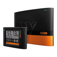
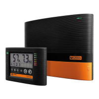
UNDERSTANDING YOUR ENERGIZER
Energizer OK Indicator
Normal operaƟ on. This light is always on when the Energizer is powered up.
Fence OK Indicator (M150/M200 model only)
Your Energizer is powering your fence line. The fence OK indicator will Ň ash with
every Energizer pulse. This indicator will stop Ň ashing if the fence is overloaded.
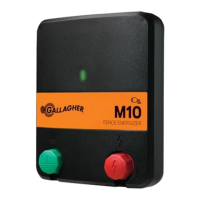
Output Voltage Bar Graph
The output voltage bar graph will pulse with every Energizer pulse. Each colour
segment gives an approximate indicaƟ on of the fence performance. The Graph is
read in the following manner:
Green Segments Your fence is performing well. No aƩ enƟ on is required.
Yellow Segments Your fence is under some load but is sƟ ll delivering an
eī ecƟ ve shock.
Red Segments Your fence is under heavy load and requires maintenance.
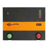
Output Voltage Indicator LCD and Output Alarm Light (M1000 model only)
• Shows the voltage at the Energizer and warns if the output voltage has fallen
below a set level.
• Output voltage indicates the quality of your fence system - the higher the
voltage the beƩ er the animal control. If Output Voltage drops below 2kV the
alarm is acƟ vated. The Output Alarm light will turn on and remain on unƟ l the
alarm is cleared. This alarm indicates the fence system is heavily loaded and at
risk of being inadequate for eī ecƟ ve animal control. Urgent fence maintenance
is required.
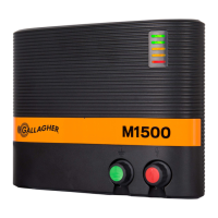
Fence Lead-out
Inadequate fence lead-out is oŌ en the reason for poor voltage on the fence.
ParƟ cularly on either larger fence systems or fence systems heavily loaded with
vegetaƟ on.
Lead-out is deĮ ned as the wire system that takes the power from the Energizer to
the centre of the fence system - not just from the Energizer to the fence! Basically,
the more wires connected in parallel, the beƩ er the voltage at
the end of the fence.
If the centre of the fence system is more than 300 Ō (100m) from
the Energizer, at least 1 x 1/8” (2.5mm) wire is required. If the
centre of the fence system is more than 5/8 mile (1km) from the
Energizer, a minimum of 3 x 1/8” (2.5mm) wires or a single High
ConducƟ ve 1/8” (2.5mm) “PowerWire” is required. Larger fence
systems or heavily loaded fence systems with large Energizers
may require more wires to adequately transfer the power from
the Energizer onto the fence system.
HANDY HINT