Chapter 4: Cell Connections--Membrane Cell Connections
4 - 3
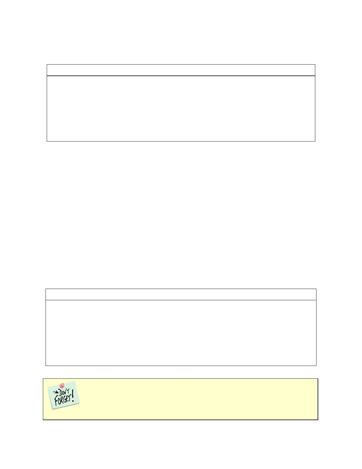
Table 4-2
Cell Cable Connections for ZRA Mode
Connect to metal sample #1
Connect to metal sample #1
Connect to a reference electrode
Connect to metal sample #2
Connect to metal sample #2
Leave open or connect to a Faraday shiel
The counter sense and the working sense lead are each connected to different metal samples. In the ZRA
mode the Interface 1000 is normally programmed to maintain zero volts between these leads. It therefore
maintains the two metal samples at the same voltage.
The white pin jack on the cell cable is normally connected to a reference electrode. The potential between this
lead and the working sense lead is reported as the cell potential.
In ZRA mode, if you do not have a reference electrode in your cell, we recommend that you connect the white
reference lead to the working electrode. In theory, the measured potential is exactly zero when this is done. In
practice, A/D noise and offset create a small potential signal with a value very close to zero.
Membrane Cell Connections
The Interface 1000 can be used with membrane cells. In this type of cell, a membrane separates two
electrolyte solutions. Two reference electrodes are used: one in each electrolyte. Each electrolyte also contains
a counter electrode. The Interface 1000 controls the potential across the membrane. Table 4-3 shows the cell
connections used with a membrane type cell.
Table 4-3
Cell Cable Connections for a Membrane Cell
Connect to reference electrode #1
Connect to counter electrode #1
Connect to counter electrode #2
Leave open (only needed in ZRA mode)
Leave open or connect to a Faraday shield
Reference electrode #1 and counter electrode #1 must be on one side of the membrane,
and reference electrode #2 and counter electrode #2 must be on the other side.