36
ELECTRIC CONVECTION OVENS
EN
2.2 - Wiring
Connection to the power main
• Connection to the power mains must be made according to the
regulations in force.
• Before connection, ensure that the mains voltage and frequency
correspond to the values shown on the oven rating plate (pict. 1),
located at the bottom of the rear panel.
A voltage variation of ± 10 % is allowed.
• The oven must be connected to the power mains permanently
using an H07RN-F-type heavy rubber cable in neoprene with wires
featuring a cross-section suitable for the maximum power demand
(see paragraph 1.4).
• An omnipolar master switch must be placed between each oven
and the mains, with at least a 3mm gap between contacts: capacity
must be suitable for the load, and it must feature devices protecting
the supply line.
• Suitable automatic high-sensitivity ground fault interrupters must be
installed to assure protection against direct and indirect contact of live
parts and fault currents towards earth according to the regulations in
force. The maximum allowed leakage current is 1 mA/kW.
• This switch must be installed in the permanent electrical system
of the facility where the appliance is installed, and in the immediate
vicinity of the actual appliance where it can be reached easily by
operators.
• Check data in the specifications table for appropriate sizing of the
supply line, master switch and cable. (see paragraph 1.4).
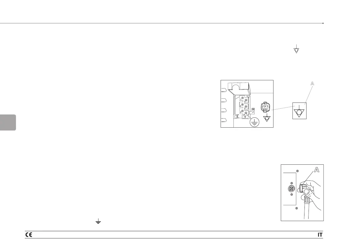
2.3 - Mains’ earth line
• The appliance must be connected to the mains’ earth line.
• For this purpose, the power terminal board is accessible on the
back of the oven, and the yellow/green wire of the power cord must
be fastened to the terminal marked (see pict. 5).
• The oven must be included in an equipotential system. Connection
must be made with a wire featuring 2 a cross-section of at least 10
mm
2
connected to the terminal (A - pict. 5) marked located on
the bottom of the oven.
• The cable must be carried to the oven installed in a metal tube with
any sharp parts suitably removed, or in a stiff plastic tube.
A
2
pict. 5
2.4 - Connection to the water supply
• Connect the water supply pipe to the 3/4” G inlet, screwing on the
coupling (A - pict. 6). Fit the circuit with a suitable
mechanical filter and a shutoff cock.
• To work properly, the ovens require drinking
water with a maximum hardness of 3 °F to
prevent scaling inside the cooking chamber.
Where necessary, install an appropriate water
softener on the water circuit’s supply line.
• The permissible supply pressure range is min.
200 kPa, max 300 kPa.
A
pict. 6
2 - Second Part_Installation instructions and maintenance