13-10-617 Page 20
WATER PIPING (Water-Cooled Heat Exchanger Models Only) - On machines equipped with water-
cooled heat exchangers, the water inlet and outlet connections are located in the unit base flange on the
left side of the unit.
It is mandatory that any water cooled unit be installed in a shelter heated to
temperatures above freezing (32° F., 0° C).
The water source should be capable of supplying up to the maximum flow shown in (Figure 2-5, Page
19), and (Figure-2-6, page19), at a minimum pressure of 40 psig (2.8 bar); maximum allowable water
pressure is 150 psig (10.3 bar). The water flow rates shown are approximate and a guide to sizing piping,
cooling tower and other water system equipment.
The heat exchanger system is designed to operate with water inlet temperatures from 60° F to 90° F (16°
C to 32° C) and a water outlet temperature not to exceed 110° F (43° C). If water cooler than 60° F is
used, high water outlet temperatures (over 110° F, 43° C) will be experienced along with shortened heat
exchanger life caused by tube fouling and corrosion. If water warmer than 90° F (32° C) is used, higher
compressor oil inlet temperatures and high water usage will result.
Most water systems will require control of impurities: filtration, softening or other treatment. See Section
5, “Compressor Oil Cooler - Water-Cooled Heat Exchanger” for more information on the water system.
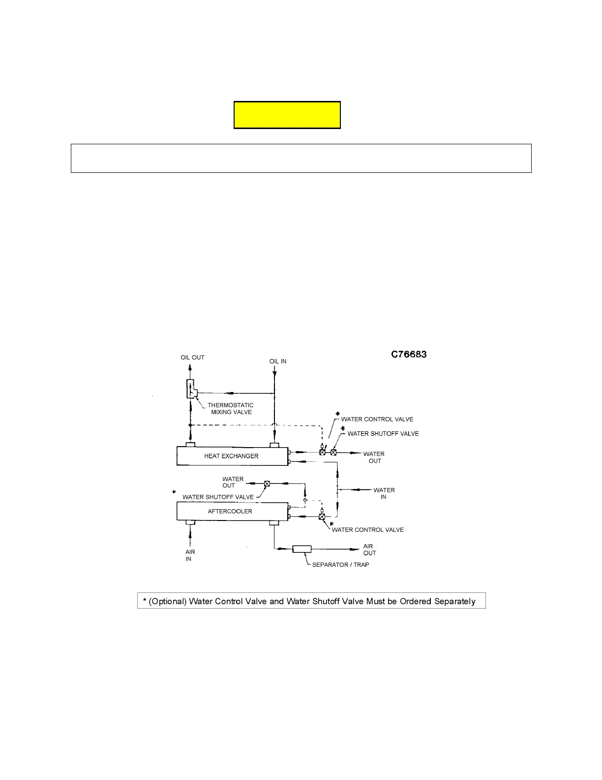
Figure 2-7 – PARALLEL PIPING (STANDARD PACKAGE)
PARALLEL PIPING (Figure 2-7) A separate water control valve is required to control the discharge air
temperature. If a remote (externally mounted) water-cooled aftercooler is piped in parallel with the heat
exchanger, provide a separate water control valve for the aftercooler and pipe separate inlet water lines
to both the aftercooler and heat exchanger.
C
C
C
A
A
A
U
U
U
T
T
T
I
I
I
O
O
O
N
N
N




 To Next Page