13-10-617 Page 35
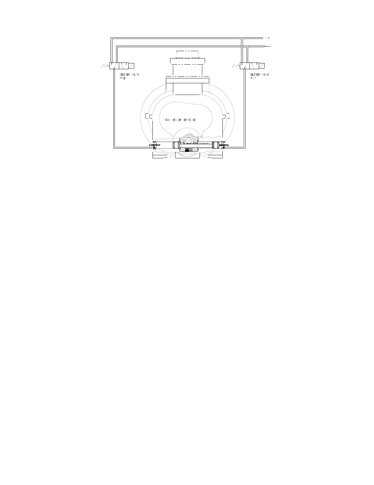
Figure 4-7 – TURN VALVE
Turn Valve (Figure 4-7) - The turn valve is a helical valve which, when rotated, opens and closes a series
of ports cast into the compressor cylinder. When these ports are open, they direct some of the air which
would otherwise be compressed back to the inlet, reducing both capacity and power consumption.
Turn Valve Actuator - The turn valve actuator is a rotary rack and pinion device which positions the turn
valve according to system demand. Filtered oil from the compressor sump is directed to the outboard
end of the two actuating cylinders to move the rack and rotate the valve. Located on the ends of the
cylinders are adjusting screws which limit the travel of the actuator. When looking at the rear of the
compressor, the adjusting screw on the right on the compressor adjusts the fully closed (full-load) position
of the valve. The full load position of the actuator may be checked by removing the adjusting screw at the
unloaded end of the actuator (left side of the compressor) and using a rod to push the pistons to the full
load position. The rod must be clean and free of burrs and scale. Take care not to scrape the cylinder
walls when moving the pistons.
Solenoid Valves TVC and TVO - These valves control the position of the turn valve in response to
signals from the “AirSmart” controller. With both valves de-energized, equal pressure is applied to both
ends of the actuator to hold it in its present position. If TVC only is energized, the right side of the turn
valve actuator is exhausted to the compressor inlet cavity, causing the turn valve to move towards the full
load position. If TVO only is energized, the left end of the turn valve actuator is exhausted to the
compressor inlet cavity, causing the turn valve to move towards the unload position. See “AirSmart”
Controller Manual, for a description of how the turn valve position is controlled during normal operation.
System Pressure Transducer - This transducer is connected after the minimum pressure valve. It
converts the pressure in the plant air system into an electrical signal for use by the “AirSmart” controller
for modulation and control.
Reservoir Pressure Transducer - This transducer is connected to the coolant system. Its signal is
used to prevent loaded starts, monitor reservoir pressure, and monitor the condition of the air/oil
separator.
Air Filter Vacuum Switch - This switch is used to monitor air filter condition and alert the user if the
filter requires service or replacement.
213ECM797-
(Ref. Drawing)




 To Next Page