13-10-617 Page 36
Discharge Thermistor - This sensor is located directly in the compressor discharge. Its signal is used
to monitor compressor temperature and shut down the compressor if a coolant problem is detected.
Reservoir Thermistor - This sensor is located near the separator and is used to monitor temperature
and shut down the compressor if high temperatures are detected.
Emergency Stop Push-Button - This is a maintained push-button, and removes power from the
controller outputs regardless of controller status. It is located on the upper section of the panel, next to
the keypad. This should be used for emergency purposes only - use the keypad [STOP/RESET] for
normal controlled stopping.
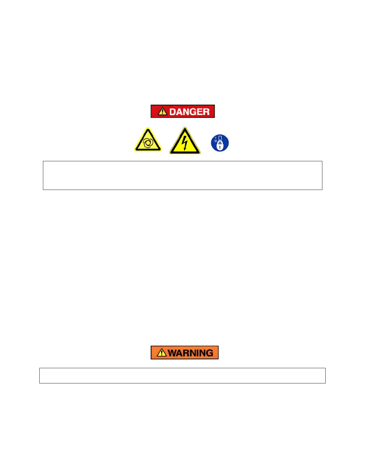
Automatic restarting or electrical shock can cause injury or death. Open,
lockout and tagout main disconnect and any other circuits before servicing
unit.
Power Supply - This device changes the incoming AC supply voltage to 24 volts DC for use by all unit
control devices. For 575 volt AC units only, a control transformer is provided to supply 230-240 volts AC
input to the power supply. A secondary fuse is provided on the control transformer. Refer to adjacent
labeling for replacement information.
Fuse Blocks - Two Class CC fuse blocks provide line side protection for the power supply and control
transformer, as applicable.
Terminal Strip - This provides connections for all 24 volt DC controlled devices not directly connected to
the “AirSmart” controller.
Fan Starter - The starter is used to provide control and overload protection for the cooling fan or the
ventilation fan of water – cooled units with enclosure. Overload heaters should be selected and adjusted
based on the motor nameplate amps and the instructions located inside the cover of the electrical
enclosure. Three fuses are provided. Refer to adjacent labeling for replacement information.
Main Starter - The main starter is to be mounted at a location selected by the user at the time of
installation. The first three feet of line from the motor conduit box to the starter must be of flexible conduit
to maintain effective vibration isolation. Electrical connections to other parts of the unit (instrument panel,
fan motor, etc.) from the starter do not require flexible conduit since the compressor and motor are
already isolated from these parts. See Article 110-16(a) National Electric Code for working clearance.
Electrical shock can cause injury or death. Open main disconnect switch, tag and lockout before
working on starter/control box.
Less starter applications utilize a control relay for control of the remote mounted motor starter (not
provided with the compressor package).




 To Next Page