13-10-617 Page 47
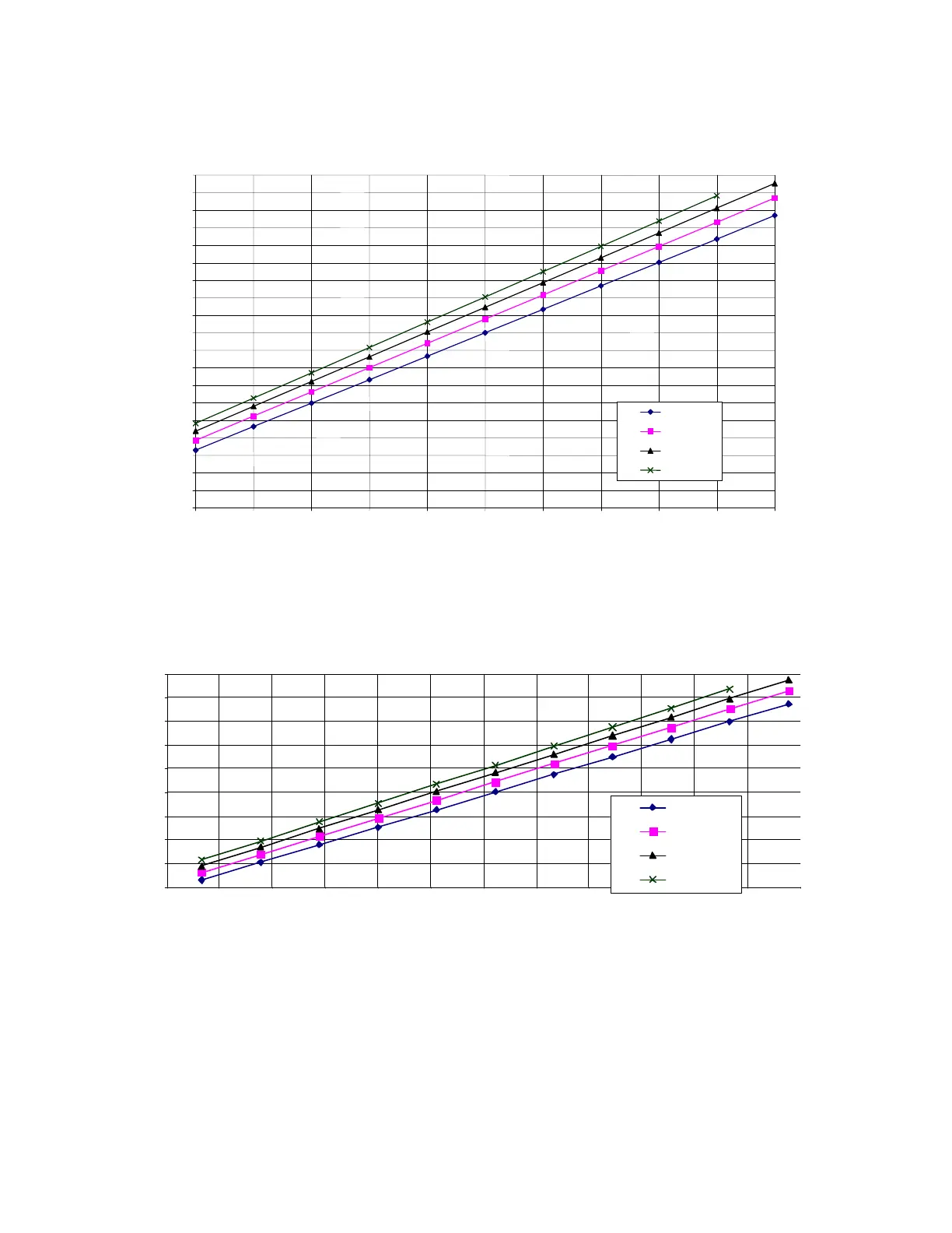
Dew-Point Temperature vs. Ambient Temperature
(100% Relative Humidity)
40
50
60
70
80
90
100
110
120
130
140
150
160
170
180
190
200
210
220
230
20 30 40 50 60 70 80 90 100 110 120
Ambient Temp. F
Dew-Point Temp. F
100 psig
125 psig
150 psig
175 psig
Figure 5-1 – DEW POINT CHART °F
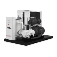
Dew-Point Temperature vs. Ambient Temperature
(100% Relativ e Humidity)
20
30
40
50
60
70
80
90
100
110
-10-5 0 5 101520253035404550
mbie nt T emp. C
Dew-Point Temp. C
6.9 bar
8.6 bar
10.4 bar
12.1 bar
Figure 5-2 – DEW POINT CHART °C
These charts are easily used by reading the ambient temperature along the bottom axis of the chart and
then reading the appropriate pressure curve to determine the corresponding dew-point temperature on
the left axis of the chart. The compressor discharge temperature must be maintained at a minimum of
10° F above this dew-point temperature to prevent condensation accumulation in the lubricant reservoir.
These charts assume 100% relative humidity
.




 To Next Page