This document serves as the Operators Manual for Gardner Denver Direct Expansion Compressed Air Dryers, providing essential information for installation, operation, maintenance, and troubleshooting. It emphasizes the importance of adhering to safety regulations and using qualified personnel for all technical operations to ensure efficient and safe use of the equipment.
Function Description
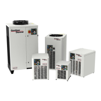
Gardner Denver refrigerated air dryers are designed to remove moisture from compressed air, which is crucial for protecting pneumatically operated appliances, controls, instruments, machinery, and tools from the detrimental effects of water. The drying process involves two stages within a patented aluminum heat exchanger. Initially, compressed inlet air is cooled by colder compressed air in an air/air sector. Subsequently, in a refrigerant/air sector, the air temperature is further lowered to the dew point. During these stages, oil and water vapors condense into liquid, which is then separated from the compressed air in a condensate separator and automatically drained. The now cold, dry air re-enters the air/air exchanger, where it is reheats by the incoming hot air. This process recovers energy and reduces the relative humidity of the outflowing air. The dryer is equipped with all necessary control, safety, and adjustment devices, eliminating the need for auxiliary equipment. While system overloads can impact operational performance (e.g., high dew point), they do not compromise the dryer's safety. The minimum protection degree is IP42.
Usage Features
The dryer is designed for use with compressed air only. Any other application requires consultation with a Gardner Denver distributor. Installation, use, and maintenance must comply with the European safety directive and the instructions provided in this manual. Due to the pressurized nature and rotating parts of the dryer, precautions similar to any machinery of this type are necessary. Operators must read all instructions before operating the unit. Only qualified personnel are permitted to adjust, perform maintenance, or repair the dryer. The main electrical disconnect switch and any separate control lines must be disconnected before working on the unit. No servicing should be attempted while the machine is operational. Pressure must be relieved from the entire air system before removing any parts. Refrigerant system parts should only be removed and contained in accordance with EPA and local regulations. The dryer must not be operated at pressures exceeding its rating or without guards, shields, and screens. Daily inspections are recommended to identify and correct unsafe operating conditions.
Upon delivery, the unit should be inspected for rough handling, and any damages noted on the delivery receipt, as this is a precondition for insurance claims. The dryer must always be kept in a vertical position during handling, using appropriate lifting equipment. Unpacking should occur after the dryer is positioned at the installation site. Heavy objects should not be lifted without proper lifting equipment.
For storage, the dryer should be kept in its packaging in a dust-free and protected environment between 0°C (32°F) and 50°C (120°F) with humidity not exceeding 90%. For storage exceeding 12 months, contact a Gardner Denver authorized distributor. The installation site should protect the machine from atmospheric agents and direct sunlight, have a flat seating base capable of supporting the dryer's weight, and maintain an ambient temperature within the dryer's nominal data. The dryer should be in a clean area, free from forced air drafts that could affect the fan control system. Sufficient clearance (500 mm or 20 inches) around the dryer is required for adequate cooling and maintenance. Incoming air must be free from smoke or flammable vapors to prevent explosion or fire risks.
Before installation, ensure no parts of the air system are under pressure or electrically powered. Tubing connected to the dryer must be free of impurities and not exert weight on the device. All interconnecting piping must be tightened. The dryer should be connected to compressed air lines, ideally with a by-pass for isolation during maintenance. Electrical connections must comply with local laws and regulations, and if the power cord lacks a plug, a disconnecting device should be installed. The condensate drainage assembly should be checked, and the drain flexible hose connected to a draining line. Since condensate may contain oil, a water-oil separator of adequate capacity is recommended for proper disposal. The dryer should be powered only after verifying that nominal voltage and line frequency match the machine's specifications. Adequate line protection and a ground terminal complying with local electrical rules must be provided. To optimize use, control instruments should be easily visible. A prefilter with a rating of at least 10 micron must be installed before the dryer; failure to do so will void the warranty. A protective device is necessary to prevent the equipment from exceeding maximum allowable pressure and temperature.
The start-up sequence involves ensuring the dryer is bypassed and without load on the cooler, then switching on the main electrical isolation switch. The control panel will display "OFF." The dryer starts by pressing and holding the local ON/OFF button, provided no active alarms are present. The compressor motor starts after 120 seconds, and the fan motor starts simultaneously for GDD37-100F models or after 30 seconds for smaller models. For GDD130-160F models, the fan motor is controlled by a pressure switch. The stop sequence involves pressing the ON/OFF switch for 1 second, after which the compressor and fan motor (on GDD130-160F, only the compressor) continue running for 10 seconds to re-balance internal pressures. Shutdown can also occur due to an alarm or energy-saving conditions (ESA or ES2). Alarms de-energize the compressor, but the fan motor may continue running (GDD4-100F models). Energy-saving conditions occur when the dew point is below the set value for an extended period, saving energy and preventing heat exchanger freezing, especially in low ambient temperatures or without compressed air load. GDD130-160F models' fan motor is controlled solely by the fan pressure switch.
Variable speed fan control (GDD4-100F models) uses a microprocessor to adjust cooling capacity by changing fan motor speed. Speed increases if the dew point is above the set value and decreases if it's below. The fan speed ranges from 0 to 100%, with "FL" indicating full load. Under normal load, fan speed is typically 100%; with no load, it oscillates between 0% and 20%. GDD37-100F models integrate a hot gas by-pass valve with the variable speed system to adjust cooling capacity.
The electronic control system features a digital panel with 5 keys (ON/OFF, TEST, SET, DOWN, UP) and a 3-digit display with three signaling LEDs. The TEST key, when held for 3 seconds during normal operation, activates the condensate drain. The SET key displays parameter C1 when pressed and released, and allows access to C8 and C9 condensate drain parameters programming menu when held for 10 seconds. It also stores new configuration values. The DOWN key decreases displayed values and initiates an automatic test cycle of the controller when held for 10 seconds during normal operation. The UP key increases displayed values. The ON/OFF key activates or deactivates the dryer, showing "OFF" when deactivated. Even when the controller is off, some parts of the dryer may still be energized; electrical power must be disconnected for safety before any operations.
Condensate discharge parameters (C8 for delay between discharges, C9 for discharge time) can be programmed by holding the SET key for 10 seconds. Changes to timing values become effective after exiting programming, while other variable changes are immediate. Modifying configuration parameters can affect efficiency and should only be done by personnel familiar with dryer operation. Unauthorized modification of other electronic controller parameters is forbidden.
The controller recognizes anomalies in the drying circuit, displaying blinking messages alternating with the current dew point. Messages like "HtA" (high dew point, delayed alarm) and "Ht2" (very high dew point, immediate alarm) indicate issues requiring attention, potentially a call to a Gardner Denver distributor. "PF1" (interruption/short circuit on PTC probe) may require probe replacement. "ESA" and "ES2" (automatic energy saving mode) are normal behaviors under low load. "ASt" (activated after repeated alarms) indicates a serious issue requiring distributor contact.
Before the first start-up and after prolonged inactivity, ensure all installation instructions are followed. Verify the dryer bypass is open and air inlet/outlet valves are closed. Activate power supply and press ON/OFF. For GDD130-160F models, turn the main power switch to position 1 and wait 8 hours before starting the dryer (essential for warranty). If the unit fails to start, check phase connections. Wait 5-10 minutes for the machine to reach standard operating parameters. Slowly open the air outlet valve, then the air inlet valve. Close the air bypass valve if present. Check condensate drain operation and ensure all connecting pipes are tightened. To stop the dryer, use the ON/OFF switch; wait 10 minutes before restarting to allow freon pressure to rebalance.
Maintenance Features
Maintenance operations require ensuring no parts of the air system are under pressure or electrically powered.
- Weekly or Every 40 Hours: Verify control panel temperature, visually check regular condensate drainage, and clean the filter mesh of the condensate drain system.
- Monthly or Every 200 Hours: Clean the condenser with compressed air, taking care not to damage fins. Check dryer operation and the condition of any filters, replacing elements as needed.
- Yearly or Every 2000 Hours: Check and replace the flexible tube for condensate drainage if damaged. Ensure all connecting pipes are tightened. Check dryer operation.
- Every 24 Months or Every 4000 Hours (GDD130-160F): Replace the fan pressure switch.
In case of component replacement, dispose of the old parts with the eventual packaging of the new part, following decommissioning guidelines. Troubleshooting and maintenance must be performed by qualified personnel. For refrigerating circuit maintenance, contact a refrigeration engineer. Normal operational behaviors include variable fan speed (GDD4-100F), "ESA" and "ES2" messages during low or no load operation, and a 2-minute delay before the dryer starts after pressing ON/OFF.
Troubleshooting guidance is provided for various issues:
- Control panel blank: Check power, cabling, and electronic control board.
- Dryer off: Turn on with ON/OFF switch.
- Dryer in stand-by: Wait 2 minutes after switching on.
- Compressed air inlet/outlet inverted: Check connections.
- Flow rate/temperature higher than nominal, or ambient temperature higher than nominal: Restore nominal conditions.
- Dirty condenser: Clean the condenser.
- Condensate drain not functioning: Clean filter mesh, replace drainage solenoid valve coil, clean/replace valve if clogged, check C8/C9 parameters, or replace no loss condensate drain.
- Temperature control probe improperly positioned or faulty: Check/replace the probe.
- High pressure switch intervention (GDD130-160F): Reset switch, check cabling/electronic control board.
- Compressor internal thermal protection activation: Wait one hour, if fault persists, stop dryer and call distributor.
- Electrical components of compressor issues: Check components.
- Defective compressor: Replace compressor.
- Fan pressure switch defective/burned out: Turn off dryer and call distributor.
- Gas leakage in refrigerating circuit: Turn off dryer and call distributor.
- Defective fan: Replace fan.
- Protection fuse burned out: Replace fuse.
- Ice formation in evaporator: Check probe, electronic control board, or gas charge.
- Clog in low pressure line: Check air inlet/outlet, connecting tubing, valves, filter condition.
- Continuous air flow through condensate drainage: Verify C8/C9 parameters, check control board signal, or replace no loss condensate drain.
- Series of alarms: Call distributor.
The temperature control probe is delicate and should not be removed from its position; contact a distributor for problems. Cleaning the drain solenoid valve involves acting on the TEST key to clean the mesh filter. The discharger body should never be removed.
Decommissioning
All decommissioning work must be carried out by specialist personnel. The procedure involves stopping the device, permanently isolating it from electricity, disconnecting the power cable, taking pressure off the air circuit, and emptying the tank and internal cooling medium circuits. If the device is to be dispatched, use original or similar packaging and keep it upright. Before working on electrical parts, ensure the main switch interrupts electricity supply and affix warning signs. Consult safety instructions for handling and storage. Remove any residual cooling medium in accordance with legislation. If demolishing the device, never open the sealed cooling assembly (compressor, evaporator, condenser) if refrigerant or lubricating oil may be present. Send the dryer to an approved waste disposal company in accordance with environmental protection legislation.