13-8-621 Page 38
8. Align sheaves with a straight edge.
9. Assemble the guards.
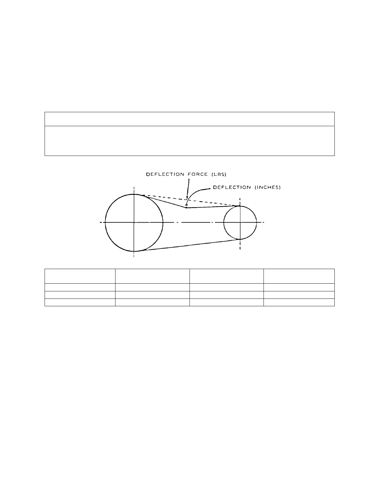
CHECKING BELT TENSION - Using a spring scale, apply a perpendicular force to each belt at the
midpoint of the span and measure the deflection. Correct deflection force and deflection are shown in
Figure 7-1. To tighten belts, merely increase the center distance.
NOTICE
When a new set of belts is installed on a drive, the initial deflection force should
be 1/3 greater than shown in Figure 7-1. Recheck tension frequently during the
first 24 hours of operation
Motor H.P.
No. of Belts
Deflection
Force Pounds
Deflection In Inches
20 4 6 – 8.5 3/8
25 4 6 – 8.5 3/8
30 4 6 – 8.5 3/8
Figure 7-1 – BELT TENSION – J SECTION MICRO-V BELTS