Do you have a question about the Garmin 010-01127-20 and is the answer not in the manual?
Overview of the manual's purpose and scope for installing GSU 75 and GMU 44.
Details the GSU 75 ADAHRS and GMU 44 Magnetometer functions and capabilities.
Outlines environmental, physical, and performance specifications for the GSU 75 and GMU 44.
Provides an overview of hardware installation for GSU 75 ADAHRS and GMU 44 into aircraft.
Lists necessary cables, hardware, and air hoses for GSU 75 and GMU 44 installation.
Specifies requirements for electrically bonding equipment, brackets, and racks to aircraft structure.
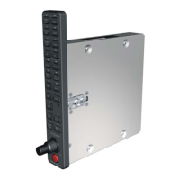
Details specific instructions and considerations for rigid and accurate mounting of the GSU 75 unit.
Guides on supplying and fabricating system cables and connectors for GSU 75 and GMU 44.
Provides instructions for mounting the GMU 44 and GSU 75 units to their respective racks.
Directs users to Section 5 for system configuration, calibration, and checkout after installation.
Details the pin assignments and I/O for the GSU 75 (J751) and GMU 44 (J441) connectors.
Explains aircraft power inputs, magnetometer power, and OAT probe power connections.
Describes various data interfaces including ARINC 429, RS-232, RS-422, and RS-485.
Outlines essential calibration procedures required before operating the GSU 75 and GMU 44.
Step-by-step guide for compensating pitch/roll offsets by leveling the aircraft.
Procedure for calibrating the magnetometer at a site free of magnetic disturbances.
Test to validate that no electronic devices interfere with the GMU 44 magnetometer operation.
| Brand | Garmin |
|---|---|
| Model | 010-01127-20 |
| Category | Avionics Display |
| Language | English |