Do you have a question about the Garmin GMA 1347D-00 and is the answer not in the manual?
Introduces the manual and the GMA 1347D installation context within aircraft.
Describes the features and capabilities of the GMA 1347D audio control system.
Lists the key functional features of the GMA 1347D audio panel.
Summarizes the various input/output interfaces available on the GMA 1347D.
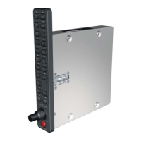
Provides dimensions, weight, and other physical attributes of the GMA 1347D unit.
Lists the electrical specifications, including power, software, and performance parameters.
Specifies the TSO/ETSO compliance for the audio panel and related equipment.
Details any granted deviations from standard TSO/ETSO requirements.
Introduces the section on installation overview and related FAA guidance.
Lists the unit part numbers and separately provided accessories for the GMA 1347D.
Details the accessories provided with the GMA 1347D unit.
Lists necessary additional equipment for the installation.
Provides guidance on the installation of the marker beacon antenna.
Advises on optimal placement for the marker beacon antenna.
Describes mounting procedures for the marker beacon antenna, including ground planes.
Offers precautions for routing and installing the marker beacon antenna coaxial cable.
Details the termination of the coaxial cable into the D-Sub connector.
Instructions for unpacking and inspecting the GMA 1347D unit upon receipt.
Refers to manufacturer instructions for installing the antenna.
Specifies requirements for BNC plug connectors on the antenna cable.
Describes how to make electrical connections using the D-subminiature connectors.
Describes the two 78-pin connectors (J3471 and J3472) on the GMA 1347D.
Introduces the pin assignment tables for connectors J3471 and J3472.
Covers power input and lighting bus pin assignments for J3472.
Explains the lighting bus inputs for configuring backlight levels.
Details the RS-232 serial communication pin assignments for J3472.
Lists pin assignments related to marker beacon operation on J3472.
Covers pin assignments for reversionary mode control with multiple GDUs.
Describes speaker output pin assignments on J3472.
Details digital audio input/output pin assignments for J3472.
Explains the PA MUTE output pin assignment on J3472.
Lists pin assignments for microphone audio inputs and key signals on J3471.
Covers remote ICS audio and key input/output pin assignments on J3471.
Details COM audio inputs and microphone key assignments on J3471.
Lists NAV audio input and ground reference pin assignments on J3471.
Describes pilot and passenger headset audio output pin assignments on J3471.
Details music input and ground reference pin assignments on J3471.
Lists unswitched audio input and ground reference pin assignments on J3471.
Covers telephone input/output pin assignments on J3471.
Details AUX, DME, and ADF audio input pin assignments on J3471.
Lists pin assignments for failsafe audio functions on J3471.
Describes summed audio output pin assignments on J3471.
| Brand | Garmin |
|---|---|
| Model | GMA 1347D-00 |
| Category | Avionics Display |
| Language | English |