Installation
20 Apollo SL30 Installation Manual
Figure 9 - SL30 NAV Power and Audio Connections
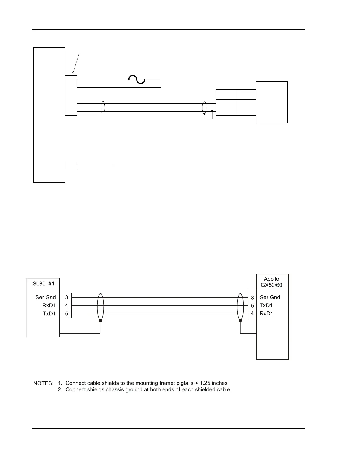
Figure 10 – SL30 to Apollo GX50/60 Connections
1
2
2 amp fuse
or breaker
+
-
Avionics
Power
Power +
Ground
NAV
Antenna
Coax cable to Nav anntena
capable of receiving both
VOR/LOC & GS
NAV Audio
Audio Gnd
23
20
SL10/15
Audio Panel
NAV 1
NAV 2
12 13
11
NAV Audio
Audio Gnd
SL30
1. Nav Audio may be left floating at the SL30.
2. Connect shields to designated ground block at the SL10/15.
3. Avionics power leads should use 20 awg wire. All others are specified at 22-24 awg.
NOTES:
37-Pin Connector
4. For NAV antenna location, refer to Figure 3, Cable Routing.
 Loading...