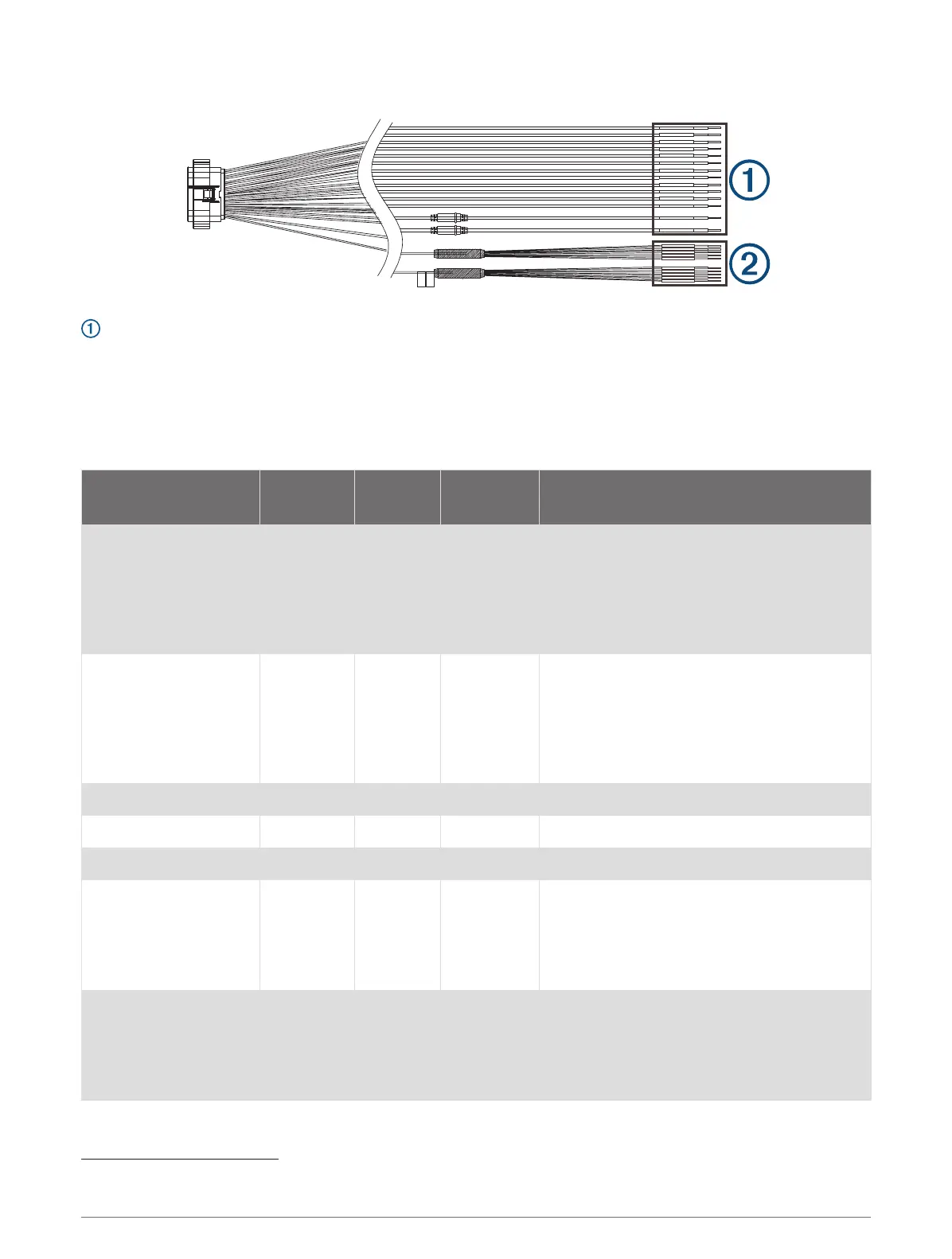
X1 Wiring Harness
X1 Primary Wire Connections
The primary wires on the X1 wiring harness connect to the appropriate devices on the vessel to allow for digital
control or monitoring. When connecting a device or devices to a wire on this harness, you must use the wire
gauge specified in the table at the very minimum. For long wire runs, you should consider using larger-diameter
(smaller gauge number) wire to minimize power loss.
NOTE: You should refer to ABYC or your local and regional standards when determining the maximum length
and gauge of wire extensions.
Wire Label Wire Color
Wire
Gauge
Software
Fuse Rating
Wire Function
CH 1-TOGGLE 1(5A) Gray 14 AWG 5A
Provides a latching switch output intended
for use with red/green navigation lights
1
.
By default this channel is tied to CH 2-
TOGGLE 2(5A) for navigation-light control
(Navigation and Anchor Light Wiring,
page 12).
CH 2-TOGGLE 2(5A) Blue 14 AWG 5A
Provides a latching switch output intended
for use with a white navigation/anchor light
1
.
By default this channel is tied to CH 1-
TOGGLE 1(5A) for navigation-light control
(Navigation and Anchor Light Wiring,
page 12).
CH 3-TOGGLE 3(5A) Orange 14 AWG 5A Provides latching a switch output
1
.
CH 4-TOGGLE 4(5A) Purple 14 AWG 5A Provides a latching switch output
1
.
CH 5-TOGGLE 5(5A) Green 14 AWG 5A Provides a latching switch output
1
.
CH 6-RES TANK 1 Pink 16 AWG N/A
Provides monitoring for tank 1 resistive
sensor.
Must connect to ground using the CH 32
TANK SENSOR GROUND wire on the X2
wiring harness.
CH 7-RES TANK 2 White 16 AWG N/A
Provides monitoring for tank 2 resistive
sensor.
Must connect to ground using the CH 32
TANK SENSOR GROUND wire on the X2
wiring harness.
1
All switches on the Garmin Boat Switch device must be configured in the chartplotter software to function properly (Switch Configuration, page 18)
7