12
Using a 4 mm hex bit or wrench, secure the front of the nose
cone to the propeller drive motor using the existing two
screws .
13
Using a 3 mm hex bit or wrench, secure the bottom of the
nose cone to the propeller drive motor using the existing
screw .
14
Using a 4 mm hex bit or wrench, secure the skeg to the
bottom of the propeller drive motor using the existing four
screws .
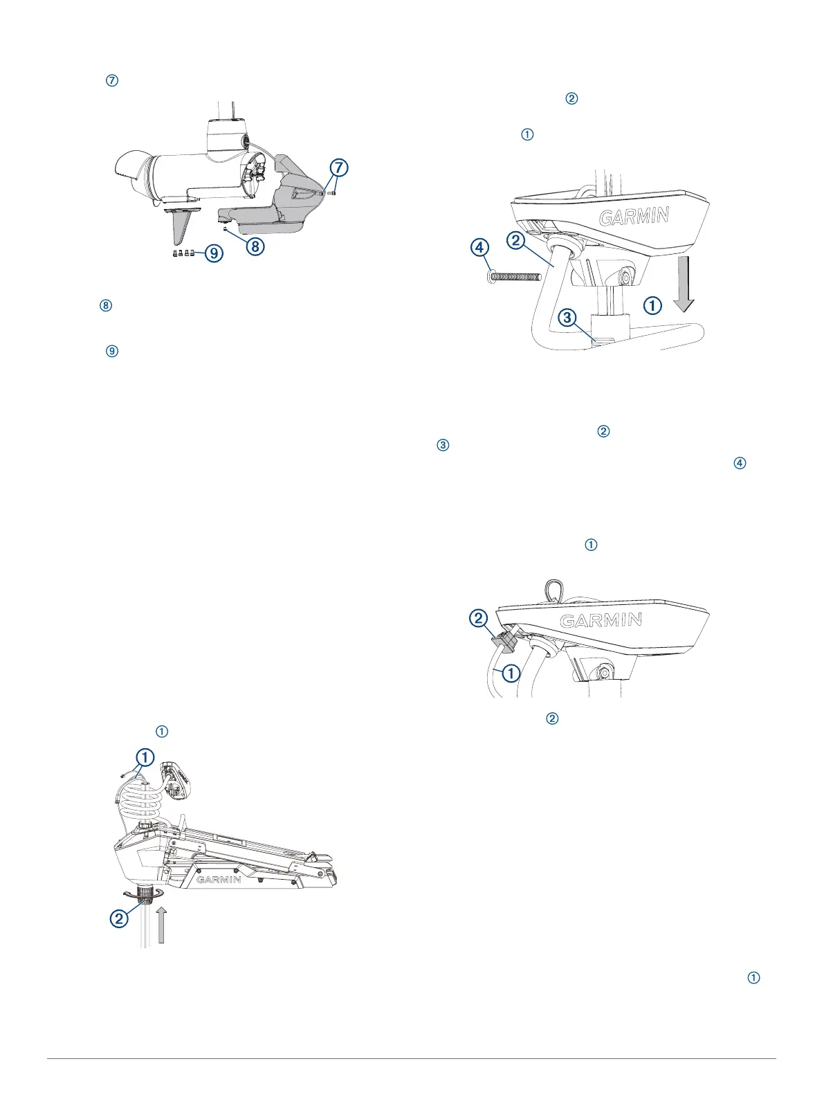
Installing the Drive Motor and Shaft
You should perform these actions to reassemble the trolling
motor after replacing the shaft or transducer.
1
Install the shaft in the steering servo housing (Installing the
Shaft in the Steering Servo Housing, page 16).
2
Install the shaft cap on the shaft (Installing the Shaft Cap,
page 16).
3
Install the transducer cable in the shaft cap (Installing the
Transducer Cable in the Shaft Cap, page 16).
4
Connect the cables in the shaft cap (Connecting the Cables
in the Shaft Cap, page 16).
5
Close the shaft cap (Closing the Shaft Cap, page 17).
6
Route the power and transducer cables through the mount
(Routing the Power and Transducer Cables Through the
Mount, page 10).
7
Connect the motor to the power source.
Installing the Shaft in the Steering Servo Housing
If you removed the depth-adjustment collar (Removing the
Depth-Adjustment Collar, page 12), you must reinstall it before
you install the shaft in the steering servo housing.
This procedure is best performed with two people.
1
2
Feed the cables up through the steering servo housing.
TIP: Depending on the height of your trailer or workbench,
you may want to move the motor mount up about halfway to
make it easier to install the shaft.
3
Insert the shaft into the bottom of the steering servo housing,
and push it up through the top.
NOTE: The shaft is keyed to fit in the steering servo housing
one way only.
4
Tighten the depth adjustment collar on the base of the
steering servo housing .
Installing the Shaft Cap
1
Pull the cables from the shaft completely through the shaft
cap.
2
Using the coil count you recorded when you removed the
shaft cap, wrap the coil cable around the shaft the
appropriate number of times.
3
Place the shaft cap on the shaft, aligning the coil cable
extending from the shaft cap with the groove on the shaft
.
4
Using a 4 mm hex bit or wrench, install the
1
/
4
-20 bolt and
nut to secure the shaft cap to the shaft.
Installing the Transducer Cable in the Shaft Cap
Before you can install the transducer cable in the shaft cap, you
must install the shaft cap (Installing the Shaft Cap, page 16).
1
Feed the transducer cable completely through the square
hole in the shaft cap.
2
Install the grommet on the transducer cable.
The grommet is split on one side to make it easy to install on
the cable.
3
Push from the outside to secure the square grommet in the
shaft cap.
4
Route the transducer cable alongside the coil cable, using
the cable clamps to hold the cables together.
5
Route the transducer cable through the mount base
alongside the coil cable, using the cable clamps to secure the
cables to the base.
6
Route the transducer cable to the chartplotter, and connect it.
Connecting the Cables in the Shaft Cap
Before you can connect the cables in the shaft cap, you must
install the shaft cap (Installing the Shaft Cap, page 16).
1
Align the rings on the ends of the cables according to color.
You must stack the red cables together and stack the black
cables together, aligning the flat sides of the connectors
on the cables.
16