GFC 600 AFCS Part 23 AML STC Maintenance Manual Page 58
190-01938-00 Revision 13
13. Press and release the CWS switch to recenter the pitch reference.
14. Rotate the NOSE UP/DN thumbwheel DN three clicks.
15. Ensure that the flight director command bars indicate a pitch down and that the pitch
servo drives the controls in a nose down direction.
16. Firmly grasp the control wheel and press the AP DISC/TRIM INT switch on the pilot’s
flight controls.
17. Verify that the pitch control moves freely.
9.4.1.3 Pitch Trim Servo Functional Check (If Installed)
NOTE: For installations with dual flight control switch installations, repeat the flight control
switch checks for the copilot flight controls.
1. Verify that the steps in Section 9.4.1 have been completed.
2. Depress both halves of the PITCH TRIM switch on the pilot’s flight controls in the NOSE
UP direction.
3. Verify that the trim runs in the nose up direction.
4. While the trim is running, depress the AP DISC/TRIM INT switch on the pilot’s flight
controls and verify that the pitch trim stops running.
5. Depress both halves of the PITCH TRIM switch on the pilot’s flight controls in the NOSE
DN direction.
6. Verify that the trim runs in the nose down direction.
7. Manually adjust the trim all the way to the nose down stop.
8. While monitoring elapsed time, actuate both halves of the PITCH TRIM Switch on the
pilot’s flight controls in the NOSE UP direction until the trim runs against the nose up
mechanical stop.
9. Verify that the elapsed time for full travel of the pitch trim is within the tolerances
specified in the appropriate model-specific installation manual addendum (190-01937-
XX).
10. While monitoring elapsed time, actuate both halves of the PITCH TRIM Switch on the
pilot’s flight controls in the NOSE DN direction until the trim runs against the nose down
mechanical stop.
11. Verify that the elapsed time for full travel of the pitch trim is within the tolerances
specified in the appropriate model-specific installation manual addendum (190-01937-
XX).
9.4.1.4 Yaw Damper Functional Check (If Installed)
1. Verify that the steps in Section 9.4.1 have been completed.
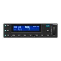
2. Engage the Yaw Damper by pressing the YD button on the GMC 605.
3. Verify that resistance is felt in the rudder pedals.




 To Next Page