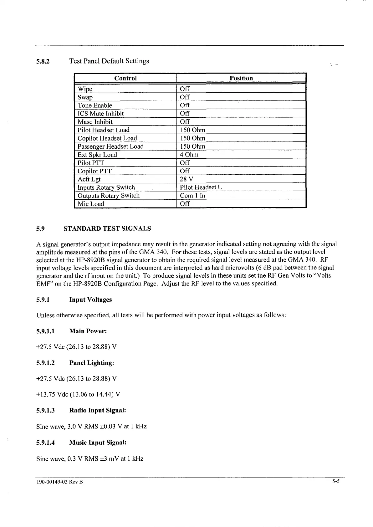
5.8.2
Test Panel Default Settings
Mic Load
I
Off
I
5.9 STANDARD TEST SIGNALS
A signal generator’s output impedance may result in the generator indicated setting not agreeing with the signal
amplitude measured at the pins
of
the GMA
340.
For these tests, signal levels are stated as the output level
selected at the
HP-8920B
signal generator to obtain the required signal level measured at the GMA
340.
RF
input voltage levels specified in this document are interpreted as hard microvolts
(6 dB
pad between the signal
generator and the rf input on the unit.)
To
produce signal levels in these units set the
RF
Gen Volts to “Volts
EMF”
on the
HP-8920B
Configuration Page. Adjust the RF level to the values specified.
5.9.1 Input Voltages
Unless otherwise specified, all tests will be performed with power input voltages as follows:
5.9.1.1 Main Power:
+27.5
Vdc
(26.1 3
to
28.88)
V
5.9.1.2 Panel Lighting:
+27.5
Vdc
(26.13
to
28.88)
V
+13.75
Vdc
(13.06
to
14.44)
V
5.9.1.3 Radio Input Signal:
Sine wave,
3.0
V
RMS
f0.03
V at
1
kHz
5.9.1.4 Music Input Signal:
Sine wave,
0.3
V
RMS
f3
mV at
1
kHz
190-00149-02
Rev
B
5-5
The document reference is online, please check the correspondence between the online documentation and the printed version.
 Loading...