Do you have a question about the Garmin GNS 430 AW and is the answer not in the manual?
Overview of the manual's purpose, scope, and intended audience.
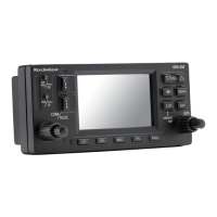
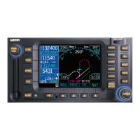
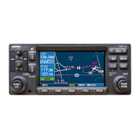
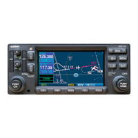
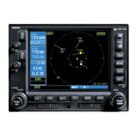
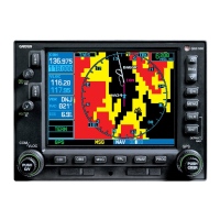
Details on the physical and functional characteristics of the 400W Series units.
Comprehensive specifications including physical, general, GPS, COM, VOR, LOC, and Glideslope data.
Guidance on following avionics installation practices and referenced AC documents.
Required components for VFR and IFR GPS/VOR/LOC/GS installations.
Information on external sensors and critical antenna mounting locations.
Considerations for unit mounting, wiring, air circulation, and safe distance.
Catalog part numbers for 400W Series units and standard kit accessories.
Details on optional accessories, enable cards, and database options.
Lists materials and special tools required but not provided for installation.
Procedures for cable installation, equipment mounting, and unit insertion/removal.
Instructions for installing COM, VOR/LOC, and Glideslope antennas.
Detailed listing of pin functions for main, COM, and NAV connectors.
Requirements for power input, lighting bus, and antenna connections.
Procedures for altitude gray code, main indicator, and VOR/ILS indicator interconnects.
Functions, electrical characteristics, and configuration of unit annunciators and switches.
RS-232 and ARINC 429 data formats and electrical characteristics for unit communication.
Audio functions and electrical characteristics for COM, VOR, and ILS audio.
Functionality and electrical characteristics of the RMI/OBI output.
DME tuning functions and electrical characteristics for the GNS 430W.
Interfaces for HTAWS audio and annunciators, including discrete I/O.
Procedures for verifying mounting, wiring, and connector engagement after installation.
Procedures for unit identification and enabling optional functions like HTAWS.
Detailed steps for configuring unit settings via ARINC 429, RS-232, system, inputs, and lighting pages.
Procedures for verifying system interfaces and instrument operations in configuration mode.
Procedures for verifying system operation, signal acquisition, and interference checks in normal mode.
Flight test procedures to verify GPS, VHF COM, NAV, and autopilot system functions.
Procedures for verifying the currency of the aviation database and replacing expired cards.
Operational limitations and software version requirements for the 400W Series units.
TSO approval conditions and aircraft compatibility requirements for installation.
Licensing requirements for operating aircraft radio stations in U.S. and international airspace.
Information on any scheduled servicing tasks or calibration requirements.
Regulatory requirements for verifying permissible indicated bearing error for VOR systems.
Guidelines for cleaning the unit and procedures for battery replacement.
Electrical interface specifications for RS-232 data output.
General format of the 400W Series RS-232 data output.
Details on the format of Type 1 output sentences.
Electrical interface specifications for RS-232 data input.
Format of the Shadin Altitude Encoder message.
Format of the Icarus Altitude Serializer message.
Format of the Shadin Fuel Flow Indicator message.
Format of the ARNAV/EI Fuel Flow Indicator message.
List of mechanical drawings included in the appendix.
List of interconnect diagrams included in the appendix.
| Voltage | 14/28 VDC |
|---|---|
| GPS Receiver | 12-channel |
| VOR/LOC | Yes |
| Glide Slope | Yes |
| Transmit Power | 10 Watts |
| Interface | RS-232 |
| Database | Jeppesen |
| COM Frequency Spacing | 25 kHz or 8.33 kHz |
| Operating Temperature | +55°C |