Do you have a question about the Garmin GNS 400W Series and is the answer not in the manual?
Guidelines for bench repair, returning units to Garmin, and spares stocking.
Information on upgrading legacy GNS 400 units to WAAS.
Steps for returning units for factory repair, including RMA requirements.
Details of product warranty terms, conditions, and exclusions.
Overview of GNS 400W series unit dimensions, features, and capabilities.
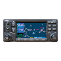
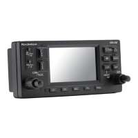
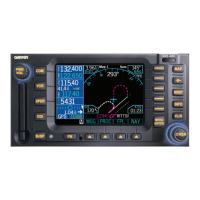
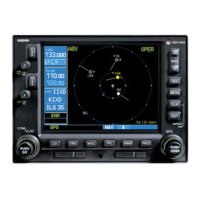
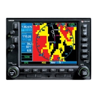
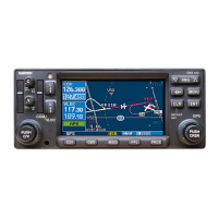
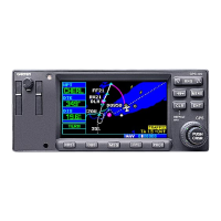
Visual guide to the front bezel layout of each unit model.
Description of the functions performed by the GPS 400W unit.
Lists the functions performed by the GNC 420W unit.
Lists the functions performed by the GNS 430W unit.
Detailed technical specifications for the GNS 400W series units.
Describes the main unit processor, interfaces, and power supplies.
Details the Main Processor, SDRAM, and NAND Flash memories.
Describes display interfaces, front panel controls, and lightning/EMI protection.
Describes interfaces for Com, Nav/Glideslope, WAAS GPS, and Inverter boards.
Details the 3-volt Lithium Battery for real-time clock and memory backup.
Describes the COM transceiver, frequency range, and transmitter options.
Details the Nav Board's functions for VOR and Localizer signals.
Describes the Glideslope Receiver operation and frequency range.
Explains the WAAS GPS Receiver's tracking capabilities for navigation.
Describes Interface Board functions and Video Board serial ports.
Describes the Keyboard's components such as snap-dome keys and LEDs.
Describes troubleshooting methods and testing procedures to identify faulty boards.
States that testing outside the manual's scope requires unit return for repair.
Explains troubleshooting by observing fault messages and recommended actions.
Describes minimum performance tests when fault message troubleshooting fails.
Explains how to display and use unit test and configuration pages.
Covers tests for Bus Power, Lighting Bus DC, memory battery, GPS Antenna Bias, Signal, and Time Mark.
Covers Display Pattern, Display Brightness, and Keyboard LED Dimming tests.
Identifies board configurations and tests unit outputs like Lateral/Vertical.
Details tests for To/From, Flag, and Super Flag signal outputs.
Covers Annunciator Outputs and Discrete Switch/Altitude Inputs tests.
Details ARINC 429 transmitter and receiver requirements and testing.
Covers RS232 Ports, GPS RS232 tests, and OBS test procedures.
Covers general test conditions and Comm Board I/O description.
Details test procedures for COMM board, including power, audio, receiver, and transmitter.
Details standard loads and signals for VOR/LOC receiver testing.
Covers tests for NAV receiver audio output, frequency response, and distortion.
Details Flag Sensitivity, Deviation Sensitivity, and Spurious Response tests.
Details standard loads and signals for glideslope receiver testing.
Lists recommended actions for main board failures during testing.
Procedures for verifying unit operation after replacement or repair.
Lists standard avionics shop tools used for part replacement.
Outlines inspection procedures to perform on an assembled unit before replacement.
Provides an overview of unit electrical/mechanical design and board location.
General procedures applicable to replacing various unit components.
Instructions for inserting and removing Jeppesen/Terrain Data Cards.
Procedure for removing and replacing the unit's top cover.
Procedures for removing and replacing the Control Display Unit (CDU) assembly.
Instructions for separating and fastening the main and nav chassis.
Procedures for removing and attaching the unit's cooling fan.
Describes replacement of Inverter Board and Comm Board in bottom cavity.
Procedures for replacing WAAS GPS Module and Main Board.
Instructions for replacing the main board's internal memory battery.
Procedures for replacing Nav Receiver and Glideslope Receiver Boards.
Procedures for cleaning the front panel and display backlight.
Lists service parts for the GPS 400W unit with reference designators.
Lists service parts for the GNC 420W unit with reference designators.
Lists service parts for the GNC 420AW unit with reference designators.
Lists service parts for the GNS 430W unit with reference designators.
Lists service parts for the GNS 430AW unit with reference designators.
Pin descriptions for the main rear panel connector (P4001).
Pin descriptions for the COM connector (GNC 420W/430W only).
Pin descriptions for the NAV connector (GNS 430W only).