EasyManua.ls Logo

Garmin GNS 430W User Manual

Garmin GNS 430W
232 pages
To Next Page IconTo Next Page
Page #1 background imageLoading...
Page #1 background image
190-00356-02 October 2008 Rev. F
400W SERIES
INSTALLATION MANUAL
GPS 400W, GNC
TM
420W/420AW, and GNS
TM
430W/430AW
GNC and GNS are trademarks of Garmin Ltd. or its subsidiaries and may not be
used without the express permission of Garmin.
Garmin International, Inc.

Table of Contents

Other manuals for Garmin GNS 430W

Questions and Answers:

Garmin GNS 430W Specifications

General IconGeneral
WAASYes
VHF Output Power10 Watts
COM Ports1
GPS Channels12
Database Update Interval28 days
TypeGPS/NAV/COM
DisplayColor
Frequency Range118.00 MHz to 136.975 MHz (COM); 108.00 MHz to 117.95 MHz (NAV)
Voltage Range11 to 33 VDC
Channels200 (NAV)
GPS ReceiverWAAS
ApproachesILS, VOR
DatabaseJeppesen
CertificationTSO-C146a

Summary

1.0 GENERAL DESCRIPTION

1.1 Introduction

Describes the physical, mechanical, and electrical characteristics for installation and approval of 400W Series panel-mounted units.

1.2 Scope

Details FAA approval for installation within airplanes type-certificated under CAR 3 or 14 CFR Part 23.

1.3 Equipment Description

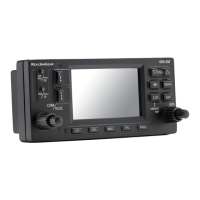
Provides details on the 400W Series units, including their display and data card slots.

1.4 Technical Specifications

Covers the technical specifications of the 400W Series units, including physical and general characteristics.

1.4 Technical Specifications

1.4.1 Physical Characteristics

Details physical specifications like bezel height, width, rack dimensions, and unit weights.

1.4.2 General Specifications

1.4.3 GPS Specifications

1.4.4 COM Transceiver Specifications

1.4.5 VOR Specifications

1.4.6 LOC Specifications

1.4.7 Glideslope Specifications

1.4.8 GPS Antenna Requirements

1.4.8.1 Antennas Without IFR GPS Operational Limitations

Lists TSO-C144 antennas meeting TSO-C146a requirements without operational limitations.

1.5 License Requirements

1.6 Regulatory Compliance

1.6.1 TSO Authorization and Advisory Circular Reference

Details TSO approval conditions, tests, and references to Advisory Circulars.

1.6.2 TSO Deviations

1.6.3 ETSO Authorization

1.6.4 ETSO Deviations

1.7 Database Options and Updates

1.7.1 Aviation Database

Information on the aviation database, its generation, conversion, and update process.

1.7.2 Terrain Database

Details on the terrain database, its update process, and download instructions.

1.9 Limited Warranty

2.1 INSTALLATION OVERVIEW

2.1 Introduction

General guidance on avionics installation practices and manual usage.

2.2 Minimum System Configuration

Details the required components for VFR and IFR GPS installations.

2.4 Antenna Considerations

2.4.1 GPS Antenna Location

Guidance on selecting the most optimum location for GPS antenna installation.

2.5 Mounting Considerations

2.5.1 Determination of Acceptable Field-of-View

Defines acceptable field-of-view for TSO C146a annunciations and GPS navigation data.

2.6 Cabling and Wiring Considerations

2.9 Installation Approval Considerations

2.9.1 Autopilot Interface Approval

Details approval conditions for interfacing autopilots with the 400W Series unit.

3.1 INSTALLATION PROCEDURES

3.1 Unit and Accessories

Lists part numbers for 400W Series units and standard kit accessories.

3.2 Optional Accessories

3.2.1 GPS Antenna Options

Provides detailed parts information for Garmin GPS antennas.

3.3 Database Options

3.6 Installation Materials Required but Not Provided

3.7 Special Tools Required

3.8 Cable Installation

3.9 Equipment Mounting

3.9.1 Rack Installation

Details dimensions and procedures for installing the mounting rack.

3.10 Antenna Installation and Connection

3.10.1 GPS Antenna

Provides information on GPS antenna cable installation and location considerations.

3.10.2 COM Antenna

3.10.3 NAV Antenna

3.12 Electrical Load Analysis

3.13 AFMS Completion – Based on Autopilot Type

4.1 SYSTEM INTERCONNECTS

4.1.1 P4001 Main Connector

Lists pin functions for the P4001 main connector.

4.1.2 P4002 COM Connector

4.1.3 P4006 NAV Connector

4.2 Power, Lighting, and Antennas

4.2.1 Power

Details power input requirements and connections for the 400W Series unit.

4.2.2 Lighting Bus

Explains lighting bus input requirements for automatic brightness adjustment.

4.2.3 Antennas

Lists antenna connector pin assignments.

4.3 Altitude Gray Code

4.4 Main Indicator

4.5 Annunciators/Switches

4.6 Serial Data

4.6.1 Serial Data Function

Describes RS-232 and ARINC 429 data formats and their functions.

4.6.2 Serial Data Electrical Characteristics

4.7 COM/VOR/ILS Audio

4.7.1 COM/VOR/ILS Audio Function

Explains COM/VOR/ILS audio activation, remote transfer, and transmit interlock functions.

4.9 RMI/OBI

4.10 DME Tuning (GNS 430W Only)

5. POST INSTALLATION CONFIGURATION & CHECKOUT PROCEDURES

5.1 Mounting and Wiring Check

Procedure to verify that all cables are secured and shields are connected correctly.

5.2 Connector Engagement Check

Steps to verify proper connector engagement before configuration and checkout.

5.3 Configuration Mode Operations

Instructions for operating in Configuration Mode and selecting/changing configuration pages.

5.3 Configuration Mode Operations

5.3.1 MAIN ARINC 429 CONFIG Page

Configures GPS ARINC 429 output and input ports, including speed and function selection.

5.3 Configuration Mode Operations

5.3.2 MAIN RS-232 CONFIG Page

Allows changing selectable RS-232 inputs and outputs to match installed equipment.

5.3 Configuration Mode Operations

5.3.3 MAIN SYSTEM CONFIG

Configures Fuel Type, Terrain Type, and Discretes options for the unit.

5.3 Configuration Mode Operations

5.3.4 MAIN INPUTS 1 Page

Monitors data on ARINC 429, RS-232, and other electrical inputs for verification.

5.3 Configuration Mode Operations

5.3.6 INSTRUMENT PANEL SELF-TEST Page

Verifies communication with other instruments and displays status information.

5.3 Configuration Mode Operations

5.3.7 MAIN LIGHTING Page

Allows setting display backlight and key lighting brightness parameters.

5.3 Configuration Mode Operations

5.3.9 MAIN DISCRETE INPUTS Page

Verifies operation of external switches and encoding altimeter input.

5.3 Configuration Mode Operations

5.3.11 MAIN CDI/OBS CONFIG Page

Verifies and calibrates MAIN CDI outputs and MAIN OBS input.

5.3 Configuration Mode Operations

5.3.13 VOR DISCRETE INPUTS Page (GNS 430W Only)

Verifies operation of external VLOC transfer switch.

5.3.14 VOR/LOC/GS CDI Page (GNS 430W Only)

Verifies and calibrates CDI outputs and OBS resolver input.

5.3 Configuration Mode Operations

5.3.15 VOR/LOC/GS ARINC 429 CONFIG Page (GNS 430W Only)

Configures VOR/ILS ARINC 429 output and input ports.

5.3 Configuration Mode Operations

5.3.16 GPS Vertical Offset

Function to enter the height above ground of the GPS antenna.

5.3 Configuration Mode Operations

5.3.17 STORMSCOPE CONFIG PAGE

Shows WX-500 Stormscope configuration as reported via RS-232.

5.3 Configuration Mode Operations

5.3.20 TRAFFIC PAGE

Displays L3 Communications SkyWatch or Ryan TCAD modes and traffic situation.

5.3 Configuration Mode Operations

5.3.21 RYAN TCAD CONFIG PAGE

Shows TCAD's current shield settings and other configuration parameters.

5.3.22 GAD 42 CONFIG PAGE

Allows remote configuration of a GAD 42 Interface Adapter Unit.

5.3 Configuration Mode Operations

5.3.24 DATA LINK DIAGNOSTICS Page

Displays GDL 69 test word for various data link parameters.

5.4 Ground Checks (Configuration Mode)

5.4.1 Main Indicator (Analog Only)

Verifies lateral/vertical deviation, flags, and TO/FROM flag using selections.

5.4 Ground Checks (Configuration Mode)

5.4.8 Lighting Bus Interface Check

Verifies that the lighting bus interface correctly varies display and key backlight levels.

5.5 Ground Checks (Normal Mode)

5.5.1 Display of Self-Test Data

Checks electrical outputs activated during the Instrument Panel Self-Test.

5.5 Ground Checks (Normal Mode)

5.5.2 Signal Acquisition Check

Verifies GPS position acquisition and reception during aircraft maneuvering.

5.5.6 Interface Checkout

5.5.6.1 Honeywell (Bendix/King) EFS40/50 Interface Check

Verifies the interface between the GNS 400W Series unit and a Honeywell EFS40/50.

5.5.6 Interface Checkout

5.5.6.2.2 Two 400W Series Units/One SN3308

Checkout procedure for two 400W Series units or one 400W and one 500W Series unit.

5.5.6 Interface Checkout

5.5.6.3 Sandel SN3500 Interface Check

Verifies the interface between a 400W Series unit and a Sandel SN3500 EHSI.

5.5.6 Interface Checkout

5.5.6.5 ARINC 429 Traffic System Interface Check

Verifies traffic interface with SkyWatch or KTA 810 TAS/KMH 820 IHAS.

5.5.6 Interface Checkout

5.5.6.9.1 XM Satellite Radio Weather Checkout Procedure

Verifies the correct interface of GDL 69/69A for XM Weather data.

5.6 Flight Checks

5.6.1 GPS Flight Check

Verifies GPS position during maneuvering and flight plan data consistency.

5.6.2 VHF COM Flight Check (GNC 420W and GNS 430W)

Ensures satisfactory performance of the communications transceiver during flight.

5.7 Database Check

5.8 Airplane Flight Manual Supplement Checks

6. TROUBLESHOOTING

6.1 Troubleshooting Procedure

Provides a guide to troubleshoot problems occurring after installation.

6.2 Alert Text Troubleshooting Procedure

6.3 Contacting the Factory for Assistance

7. LIMITATIONS

7.1 Operations

Discusses operational limitations related to Part 23 aircraft, TSO qualifications, and AFMS.

7.1.1 TSO-C146a GPS/WAAS Limitations

7.1.2 Safety Assessment Considerations

7.3 Rotorcraft Installation

8. PERIODIC MAINTENANCE

8.1 Equipment Calibration

States that no scheduled servicing tasks are required for the 400W Series unit.

8.2 VOR Checks

References CFR 14 paragraph 91.171 for permissible indicated bearing error verification.

8.3 Cleaning

Provides instructions for cleaning the unit's bezel, keypad, and display.

8.4 Battery Replacement

Details the internal battery, its replacement, and warnings about lithium batteries.

Appendix A ENVIRONMENTAL QUALIFICATION FORM

Appendix B STC DATA

B.1 STC Information

Information on STC SA01933LA, Approved Model List, and Master Data List availability.

B.4 STC Approved Model List

Lists approved aircraft models for installation based on AML STC SA01933LA.

Appendix C RESERVED

Appendix D 400W SERIES RS-232 AVIATION DATA FORMAT

D.1 Electrical Interface

Specifies RS-232 electrical interface compatibility and data generation parameters.

D.2 General Output Format

Describes the general format of the 400W Series RS-232 data output.

D.3 Output Sentence Type 1

Details the general format for Type 1 output sentences.

Appendix E 400W SERIES RS-232 FUEL/AIR DATA INPUT FORMAT

E.1 Electrical Interface

Specifies RS-232C electrical interface and data input parameters.

E.2 Shadin Altitude Sentence

Describes the 17-byte message format from Shadin Altitude Encoders.

Appendix F MECHANICAL DRAWINGS

F.1 Drawing List

Lists the mechanical drawings included in this appendix.

Appendix G APPROVED EQUIPMENT

G.1 Audio Panels

Lists approved audio panels and conditions for approval.

G.2 Air Data Computer

Lists approved Air Data Computers and conditions for approval.

G.4 Autopilots

G.5 Encoding Altimeter or Blind Encoder (Gray Code)

G.6 EFIS Displays

G.7 EHSI

Appendix H STC APPROVED INSTALLATION DIAGRAMS

H.1 Introduction

Introduction to equipment interconnect diagrams approved per AML STC SA01933LA.

H.2 Drawing List

Lists the interconnect diagrams included in this appendix.

Related product manuals