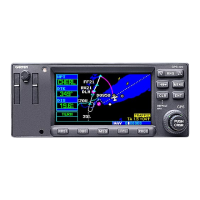
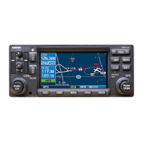
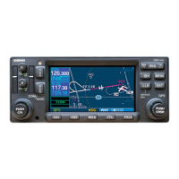
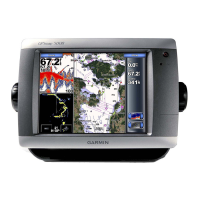
The Garmin 400W Series is a sophisticated GPS/WAAS Nav/Com unit designed for installation in Bell 407 rotorcraft, enhancing their avionics capabilities. This device integrates a color multi-function display, a Nav and Com transceiver, and a GPS/WAAS navigator into a single, compact unit, typically mounted in the center console. Its primary function is to provide comprehensive navigation and communication services, leveraging GPS/WAAS technology for precise positioning and navigation. The unit is designed to interface with other aircraft systems, such as the Garmin G500H system GDU 620 PFD/MFD, to display navigation information and Hazardous Terrain Awareness and Warning System (HTAWS) annunciations.
Usage features of the 400W Series include a user-friendly interface with easily accessible controls for managing its various functions. The integrated display allows pilots to view critical navigation data, communication frequencies, and other relevant information at a glance. For enhanced safety, the system can support optional remote HTAWS annunciators and cyclic stick switches, enabling remote control of COM and HTAWS functions directly from the pilot's controls. This integration streamlines cockpit operations and improves situational awareness, particularly in demanding flight environments. The system's ability to display HTAWS information is crucial for preventing controlled flight into terrain (CFIT) by alerting the pilot to potential hazards.
The 400W Series units are designed with internal self-test capabilities, automatically executing a thorough self-test upon power application and continuously running built-in tests during operation. Any detected internal failures or errors are indicated via failure annunciations on the equipment, prompting the pilot or maintenance personnel to investigate.
Maintenance features are detailed to ensure the continued airworthiness of the installed system. Periodic maintenance inspections are primarily "on condition," meaning they are performed as needed, with specific visual inspections and electrical bonding tests scheduled at defined intervals. For instance, a visual inspection of the 400W Series unit and its wiring harnesses is recommended every 12 months to check for signs of wear, deterioration, or damage, ensuring installation integrity. This includes inspecting the security of attachment, legibility of knobs and buttons, condition of wiring and clamping, proper sealing and attachment of related antennas, integrity of shield terminations, and signs of corrosion on equipment and racks.
The mounting rack for the 400W Series unit also requires a 12-month inspection for excessive wear, corrosion, or damage, with particular attention to cracks in the corners and the integrity of the connector plate attachment. Fasteners securing the mounting rack to the rotorcraft structure should be checked for tightness and re-torqued if necessary. If any damage is found, the mounting rack should be replaced.
The avionics cooling fan, crucial for the unit's longevity, also requires a 12-month visual inspection for signs of deterioration or damage to its wire harness and connector, as well as for corrosion on its mounting brackets.
More extensive maintenance, such as electrical bonding tests, is required every 2000 flight hours or ten years, whichever comes first. For the 400W Series mounting rack, this involves removing the unit, measuring resistance between the rack and a nearby aircraft metallic structure (verifying it's less than 10 milliohms), and, in case of failure, cleaning mating surfaces and re-verifying resistance (aiming for less than or equal to 2.5 milliohms). Similar bonding tests are prescribed for GPS antennas and HTAWS annunciators, involving disconnection of cables, resistance measurements, and cleaning of mating surfaces if a failure occurs.
Cleaning the front panel, keypad, and display is recommended using a soft cotton cloth dampened with clean water, avoiding chemical-cleaning agents to prevent scratching. The display backlight lamp has a rated usable life of 20,000 hours, and while not a scheduled replacement item, users should contact a Garmin factory repair station if the display brightness becomes inadequate. The internal keep-alive battery, which lasts about 10 years, is used for GPS system information and should be replaced by a Garmin factory repair station within 1-2 months of a "low battery" message appearing.
Troubleshooting information is extensively provided, guiding users through various alert texts and possible causes, offering solutions ranging from checking power connections and wiring to verifying antenna installations, resolving interference, and reconfiguring settings. For instance, if the unit does not power on, solutions involve checking power connections, circuit breakers, and the main avionics switch. If GPS signals are low, troubleshooting steps include checking antenna installation, cable routing, ensuring a clear view of the sky, and addressing RF interference.
Removal and installation procedures are straightforward, involving a hex drive tool for the 400W Series unit and screws for antennas and the cooling fan. After removal and reinstallation, a power-up self-test and verification of no failure messages are required. If a new or repaired unit is installed, software versions must be verified, and post-installation configuration and checkout procedures completed.
Special inspection requirements include a post-lightning strike inspection for the GPS antenna installation to check for structural damage and verify normal GPS satellite information display. A post-hard landing inspection requires completing all periodic maintenance inspections. The system does not have a defined overhaul period, relying on its continuous self-monitoring capabilities.