Do you have a question about the Garmin GPS-III+ and is the answer not in the manual?
Essential for proper screw grip to avoid damage during disassembly.
Tools like de-soldering gun or braid for removing solder.
Equipment for precise soldering work on the circuit board.
Material required for making electrical connections.
Used for trimming component leads after soldering.
Specific replacement battery model required for the device.
Unscrew the six screws located on the back of the device case.
Gently separate the case halves, being cautious of the internal connector cable.
Gently pry up the white cable connector from the circuit board.
Identify the battery on edge, next to a capacitor, left of the white connector.
Pull back the plastic clamp on the brown ribbon cable to its stops.
Unscrew the screw near the metal can on the antenna end of the board.
Gently tip the board up, hinging on the ribbon cable edge to detach it.
Turn the board over and remove solder from the battery connection points.
Detach the old battery and clean the connection holes in the pad.
Insert the new battery, ensuring the positive side faces the antenna end.
Solder the new battery leads securely and trim any excess.
Replace the board, slide ribbon cable into clamp, set in place, and install screw.
Replace the white cable clamp to secure the ribbon cable.
Ensure antenna wire is not pinched, then reassemble and install case screws.
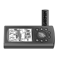
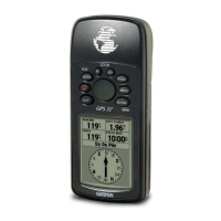
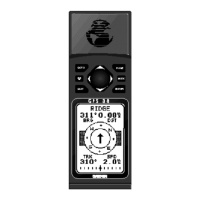
This document outlines the procedure for replacing the backup battery in a Garmin® GPS-III+ device. The primary function of this guide is to provide detailed instructions for users encountering a "backup battery has lost charge" screen message, indicating the need for a battery replacement.
The Garmin® GPS-III+ is a GPS device that utilizes a backup battery to retain stored information such as waypoints. When this battery loses charge, the device prompts the user to replace it. The replacement process, as described, involves intricate steps of disassembling the device, desoldering the old battery, and soldering a new one. It's crucial to note that removing the backup battery will result in the deletion of all waypoints and other stored information, implying that the backup battery's primary function is data retention during power loss or main battery changes.
Overall, this document serves as a comprehensive maintenance manual for a specific, somewhat advanced, repair on the Garmin® GPS-III+ device, emphasizing the necessary tools, skills, and careful execution required.