190-00906-00 GTX 33 Installation Manual
Rev. F Page 2-7
2.7 GTX 33 Mounting Requirements
The GTX 33 mounting surface must be capable of providing structural support and electrical bond to the
aircraft to minimize radiated EMI and provide protection from High-Intensity Radiation Fields (HIRF).
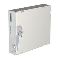
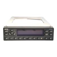
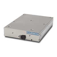
The GTX 33 and GTX 33D can be mounted using the G1000 main system rack, or may be mounted
remotely if desired. Figure 2-2 shows the GTX 33 G1000 unit rack. The unit rack is fastened to the main
system rack using the nutplate kit listed in Section 2.2.1. Refer to Figure B-2, GTX 33 Connector/Rack
Assembly Drawing, for nutplate placement locations. The installer must provide any additional remote
mounting equipment.
2.7.1 Remote Mounted Stand-Alone Rack Considerations
Figure 2-3, Figure B-3, and Figure B-4 show the GTX 33 remote mounted stand-alone racks. The remote
racks can be installed in a variety of locations, such as the electronics bay, under a seat or on an avionics
shelf behind the rear baggage area. Refer to Figure 2-5 for suggested location. Leave sufficient clearance
between the GTX 33 and any obstruction. Install the rack in accordance with AC 43.13-2B Chapter 2
“Communication, Navigation, and Emergency Locator Transmitter System Installations”. The rack should
be mounted to a surface known to have sufficient structural integrity to withstand additional inertia forces
imposed by a 4.3-pound (1.95 kg) GTX 33 unit, rack, and connectors (see Section 1.7.1 for weight
information). If it is necessary to build a shelf or bracket to mount the GTX 33 stand-alone rack or it is not
certain that the chosen location is of sufficient structural integrity, refer to Appendix A for validation of
rack mounting structures and determining static load capability.
Figure B-3 gives the stand-alone rack dimensions for the GTX 33 and GTX 33D. The rack can be mounted
vertically using four 8-32 pan head screws (MS35206, AN526 or other approved fastener). It can also be
mounted horizontally using four 6-32 100° counter-sunk flathead screws (MS24693, AN507R or other
approved fastener). Ensure that the GTX 33 chassis has a ground path to the airframe by having at least one
mounting screw in contact with the airframe. If more water-resistance is desired, the rack should be
installed in the upright vertical orientation only, otherwise, the rack may be mounted in either vertical or
horizontal orientation.
Figure 2-4 shows the stand-alone rack used for GTX 33H and GTX 33DH installations. Figure B-4 gives
the stand-alone rack dimensions for the GTX 33H and GTX 33DH. The rack can be mounted in any
orientation using screws as defined in Section 2.2.2. Ensure that the GTX 33 chassis has a ground path to
the airframe by having at least one mounting screw in contact with the airframe. If more water-resistance is
desired, the rack should be installed in the upright vertical orientation only, otherwise, the rack may be
mounted in either vertical or horizontal orientation.
After the cable assemblies are made and wiring installed to the rack back plate, route wiring bundle as
appropriate. Use cable ties to secure the cable assemblies and coax to provide strain relief for the cable
assemblies.
 Loading...